GR740-UM-DS, Nov 2017, Version 1.7 354 www.cobham.com/gaisler
GR740
29.3 Registers
The core is programmed through one register mapped into APB address space.
29.3.1 Temperature sensor control register
Table 448.0x00 - CTRL - Control register
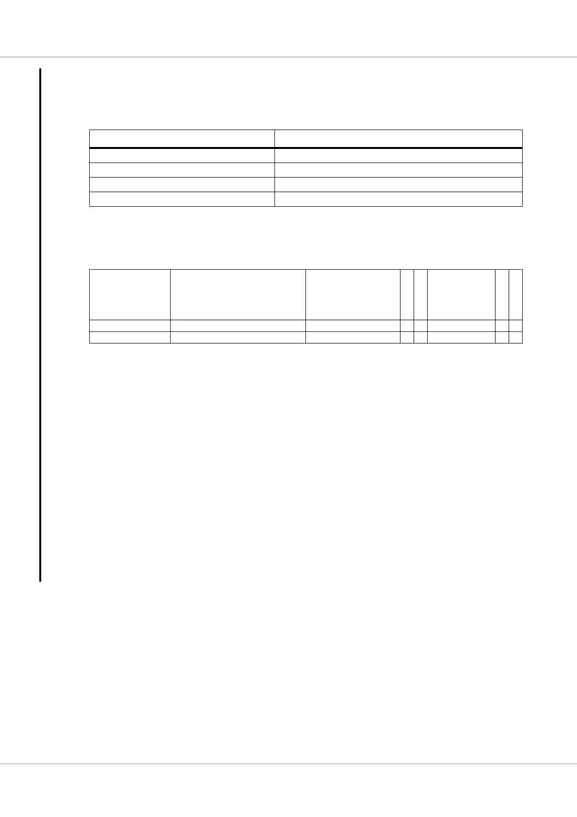
Table 447.Temperature sensor registers
APB address offset Register
0x00 Temperature sensor control register
0x04 Temperature sensor status register
0x08 Temperature sensor threshold register
0x0C - 0xFF Reserved
31 26 25 16 15 9 8 7 6 2 1 0
RESERVED DIV RESERVED A
L
E
N
P
D
N
DCORRECT S
R
S
T
N
C
L
K
E
N
0 0 0 00000
r rw r rw rw rw rw rw
31: 26 RESERVED
25: 16 Divider value (DIV) - Divider value used to generate the temperature sensor clock input from the
system clock.
The temperature sensor will be clocked with the frequency = (System clock frequency)/(2*DIV).
Allowable input clock frequencies for the temperature sensor is 125 kHz to 250 kHz. A suitable DIV
value can be calculated with DIV = (System clock frequency in Hz) / 400000.
15: 9 RESERVED
8 Alarm enable (ALEN) - When this field is set to ’1’ and a DATA value which is bigger-or-equal-than
the Threshold register’s THRES value then the ALACT field in the status register will get set.
7 Power-down (PDN) - The value of this register is connected to the active-low power-down input of
the temperature sensor.
6: 2 Offset correction (DCORRECT) - This field shall be initialised to 0b00011 = 3.
1 Sensor reset (SRSTN) - The value of this register is connected to the active-low reset input of the
temperature sensor.
0 Clock/Core enable (CLKEN) - When this field is set to ’1’ then the temperature sensor clock will be
generated based on the DIV value in this register.