GR740-UM-DS, Nov 2017, Version 1.7 36 www.cobham.com/gaisler
GR740
4 Clocking and reset
4.1 Clock inputs
The table below specifies the clock inputs to the device.
The design makes use of clock multipliers to create the system clock, memory interface clock, and the
SpaceWire transmitter clock.
4.2 Clock loop for SDRAM
Due to the drive strength limitations, the device may not be suitable to feed the clock directly to
SDRAMs at higher speeds. The device therefore implements a clock looping scheme for the SDRAM
clock, where the generated SDRAM clock goes out on either the single-ended MEM_CLK_OUT or
the differential MEM_CLK_OUT_DIFF output, should then on the PCB be split and fed both to the
SDRAM and back to the device’s mem_clk_in input. In the device, the MEM_CLK_IN input clocks
both the SDRAM interfacing registers as well as the SDRAM controller. See figure 1.
Both the differential and single-ended clock outputs are on by default after reset, software can during
boot disable the output that is unused in order to avoid unnecessary switching activity.
While what is described above is the intended usage, technically there is no requirement that the clock
fed to the MEM_CLK_IN input is related in frequency or phase to the clock going out the loop or any
other clock in the system. Other ways of generating the SDRAM clocks such as external PLL:s are
also possible.
Note: The external feedback loop is always required, no matter which clock source that is selected.
The memory controller SDRAM domain is never clocked internally, only through MEM_CLK_IN.
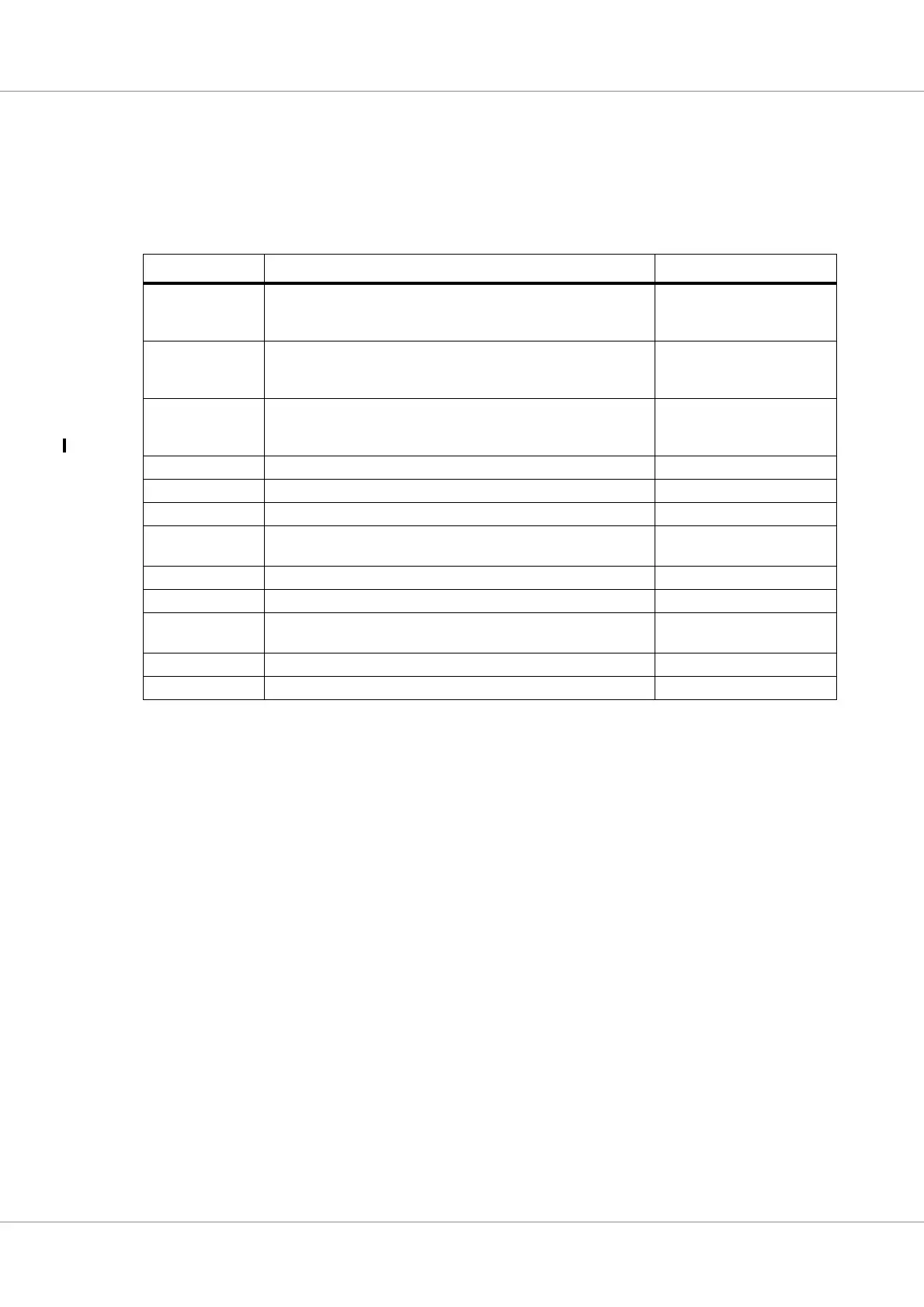
Table 29. Clock inputs
Clock input Description Recommended frequency
SYS_CLK System clock input. A clock based on this clock input via PLL
(unless PLL is bypassed) is used to clock the processors, on-chip
buses and on-chip peripherals.
50 MHz
MEM_EXTCLK Alternative memory interface clock. Clock that either directly, or
through a PLL, provides an alternative clock for the SDRAM mem-
ory interface. See description in table 23, section 3.1.
50 MHz
SPW_CLK SpaceWire clock. Clock that either directly, or through a PLL (rec-
ommended operating mode), provides a clock for the SpaceWire
interfaces. See also sections 13.3.1.2 and 13.3.2.
50 MHz
JTAG_TCK JTAG clock 10 MHz
ETH0_GTXCLK Ethernet Gigabit MAC 0 clock 125 MHz
ETH0_TXCLK Ethernet MAC 0 transmit clock 25 MHz
ETH0_RXCLK Ethernet MAC 0 receive clock 25 MHz (MII)
125 MHz (GMII)
ETH1_GTXCLK Ethernet Gigabit MAC 1 clock 125 MHz
ETH1_TXCLK Ethernet MAC 1 transmit clock 25 MHz
ETH1_RXCLK Ethernet MAC 1 receive clock 25 MHz (MII)
125 MHz (GMII)
PCI_CLK PCI interface clock 66 or 33 MHz (TBD)
GR1553_CLK MIL-STD-1553B interface clock 20 MHz