GR740-UM-DS, Nov 2017, Version 1.7 326 www.cobham.com/gaisler
GR740
23.7 Registers
The core is controlled through registers mapped into APB address space.
23.7.1 UART Data Register
Table 414. UART data register
23.7.2 UART Status Register
Table 415. UART status register
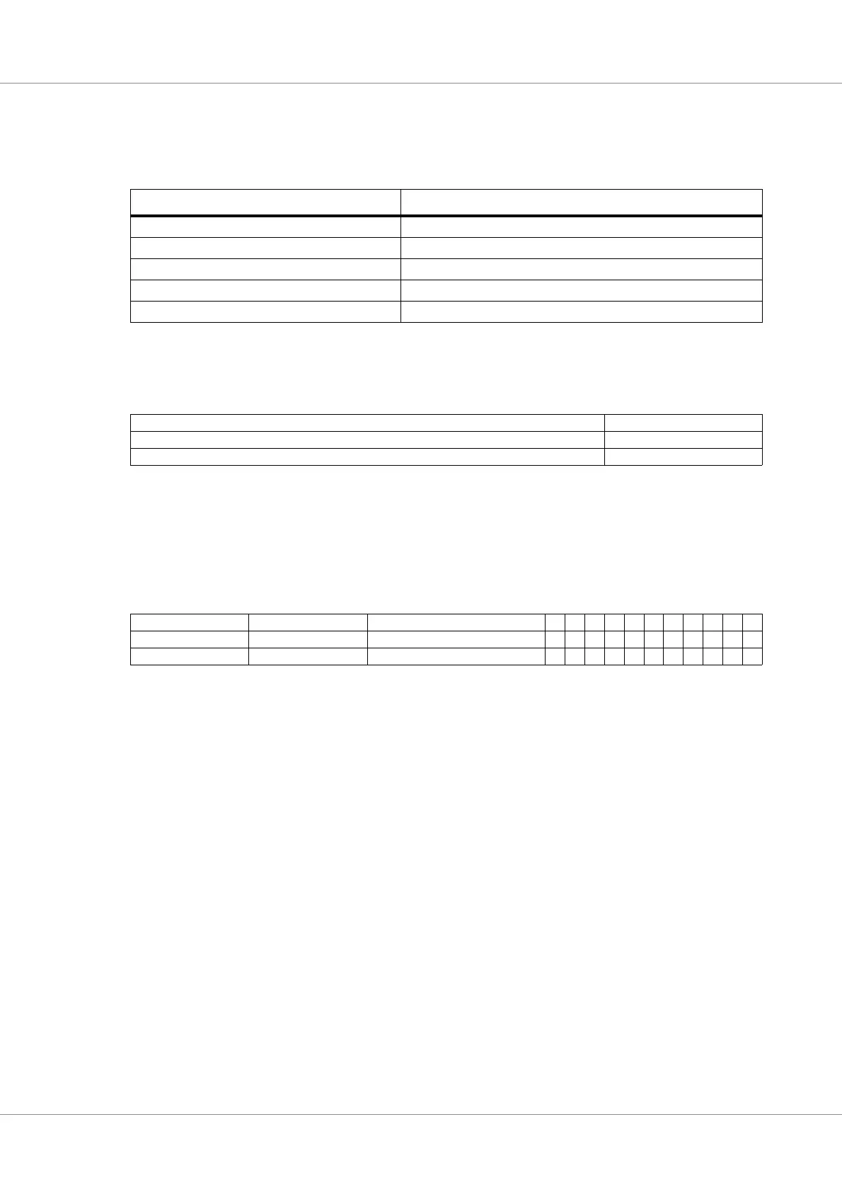
Table 413.UAR
T registers
APB address offset Register
0x0 UART Data register
0x4 UART Status register
0x8 UART Control register
0xC UART Scaler register
0x10 UART FIFO debug register
31 87 0
RESERVED DATA
N/R
rw*
7: 0 Receiver holding register or FIFO (read access)
7: 0 Transmitter holding register or FIFO (write access)
31 26 25 20 19 11 10 9 8 7 6 5 4 3 2 1 0
RCNT TCNT RESERVED RF TF RH TH FE PE OV BR TE TS DR
0 0 00000000110
r r rrrrrwrwrwrwrrr
31: 26 Receiver FIFO count (RCNT) - shows the number of data frames in the receiver FIFO.
25: 20 Transmitter FIFO count (TCNT) - shows the number of data frames in the transmitter FIFO.
10 Receiver FIFO full (RF) - indicates that the Receiver FIFO is full.
9 Transmitter FIFO full (TF) - indicates that the Transmitter FIFO is full.
8 Receiver FIFO half-full (RH) -indicates that at least half of the FIFO is holding data.
7 Transmitter FIFO half-full (TH) - indicates that the FIFO is less than half-full.
6 Framing error (FE) - indicates that a framing error was detected.
5 Parity error (PE) - indicates that a parity error was detected.
4 Overrun (OV) - indicates that one or more character have been lost due to overrun.
3 Break received (BR) - indicates that a BREAK has been received.
2 Transmitter FIFO empty (TE) - indicates that the transmitter FIFO is empty.
1 Transmitter shift register empty (TS) - indicates that the transmitter shift register is empty.
0 Data ready (DR) - indicates that new data is available in the receiver holding register.