GR740-UM-DS, Nov 2017, Version 1.7 429 www.cobham.com/gaisler
GR740
36 AHB Trace buffer tracing Master I/O AHB bus
36.1 Overview
The trace buffer consists of a circular buffer that stores AMBA AHB data transfers performed on the
Master I/O AHB bus. The address, data and various control signals of the AHB bus are stored and can
be read out, via the core’s interface attached to the Debug AHB bus, for later analysis. Note that the
LEON4 Debug Support Unit (DSU4) also includes an AHB trace buffer, tracing the Processor AHB
bus.
The trace buffer will, together with all other cores on the Debug AHB bus, be gated off when the
Debug AHB bus is disabled via the external DSU_EN signal.
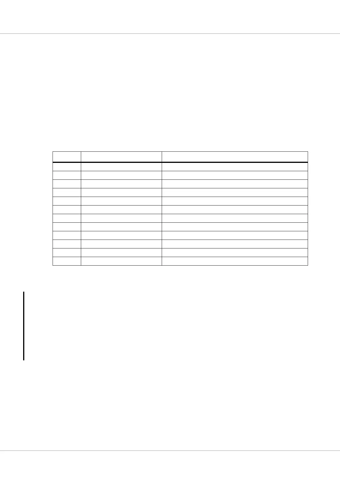
The trace buffer is 128 bits wide, the information stored is indicated in the table below:
In addition to the AHB signals, a 32-bit counter is also stored in the trace as time tag. The time tag
value is taken from the debug support unit and the debug support unit timer must be enabled for this
value to increment. The same timer source is also activated when at least one of the processors has the
up-counter, described in section 6.10.4, enabled. If the DSU’s AHB trace buffer control register’s DF
bit is set, then the timer will be stopped when the processors enter debug mode. This can be overrid-
den by clearing the DF bit or by setting the TE bit in the DSU AHB trace buffer control register, see
section 33.6.7.
Note that when the processors enter debug mode and stop execution, DMA traffic may still be ongo-
ing on the Master I/O bus. If the DSU is configured to stop the time tag counter when the processors
enter debug mode, then accesses occurring on the Master I/O bus after the processors have stopped
will receive the frozen time stamp. As previously described, his can be avoided by setting the TE bit
in the DSU AHB trace buffer control register, see section 33.6.7.
36.2 Operation
The 1 KiB trace buffer is enabled by setting the enable bit (EN) in the trace control register. Each
AMBA AHB transfer is then stored in the buffer in a circular manner. The address to which the next
transfer is written is held in the trace buffer index register, and is automatically incremented after each
transfer. Tracing is stopped when the EN bit is reset, or when a AHB breakpoint is hit. An interrupt is
generated when a breakpoint is hit.
Table 564.AHB Trace buffer data allocation
Bits Name Definition
127:96 Time tag The value of the time tag counter
95 AHB breakpoint hit Set to ‘1’ if a AHB breakpoint hit occurred.
94:80 Hirq AHB HIRQ[15:1]
79 Hwrite AHB HWRITE
78:77 Htrans AHB HTRANS
76:74 Hsize AHB HSIZE
73:71 Hburst AHB HBURST
70:67 Hmaster AHB HMASTER
66 Hmastlock AHB HMASTLOCK
65:64 Hresp AHB HRESP
63:32 Load/Store data AHB HRDATA or HWDATA
31:0 Load/Store address AHB HADDR