GR740-UM-DS, Nov 2017, Version 1.7 35 www.cobham.com/gaisler
GR740
3.5 Pin driver configuration
The drive strength of the single-ended outputs in the device are software programmable through the
general-purpose register bank (see section 30).
LVDS drivers that are not used in the application can be turned off to save power. This is controlled
via the register bank interface. Note that there is no automatic turning off of the LVDS drivers of dis-
abled or inactive SpaceWire links in this device, so this must be managed by the application software.
Applications not using the SpaceWire router at all are recommended to disable all Spacewire LVDS
drivers during boot.
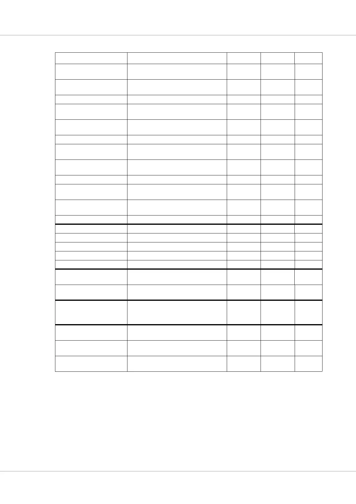
GR1553_BUSARXP MIL-STD-1553 Bus A receiver positive
input
See 3.3.1 In High
GR1553_BUSARXN MIL-STD-1553 Bus A receiver negative
input
See 3.3.1 In High
GR1553_BUSATXIN MIL-STD-1553 Bus A transmitter inhibit No Out High
GR1553_BUSATXP MIL-STD-1553 Bus A transmitter positive
output
See 3.3.1 Out High
GR1553_BUSATXN MIL-STD-1553 Bus A transmitter negative
output
See 3.3.1 In High
GR1553_BUSBRXEN MIL-STD-1553 Bus B receiver enable See 3.3.1 Out High
GR1553_BUSBRXP MIL-STD-1553 Bus B receiver positive
input
See 3.3.1 In High
GR1553_BUSBRXN MIL-STD-1553 Bus B receiver negative
input
See 3.3.1 In High
GR1553_BUSBTXIN MIL-STD-1553 Bus B transmitter inhibit No Out High
GR1553_BUSBTXP MIL-STD-1553 Bus B transmitter positive
output
See 3.3.1 Out High
GR1553_BUSBTXN MIL-STD-1553 Bus B transmitter negative
output
See 3.3.1 Out High
GR1553_CLK MIL-STD-1553 interface clock No In -
SPI_MISO SPI controller, master input, slave output No BiDir -
SPI_MOSI SPI controller, master output, slave input No BiDir -
SPI_SCK SPI controller, clock No BiDir -
SPI_SEL SPI controller, SPI select No In Low
SPI_SLVSEL[1:0] SPI controller, slave select No Out Low
CAN_RXD[1:0] CAN controller, receive data (shares pin
with PROM/IO interface)
See 3.3.1 In -
CAN_TXD[1:0] CAN controller, transmit data (shares pin
with PROM/IO interface)
See 3.3.1 Out -
TESTEN Test enable signal.
This signal puts the device in test mode.
Connect to ground.
No In High
PLL_BYPASS[2:0] Bypass PLL. See description of bootstrap
signals.
No In High
PLL_IGNLOCK Ignore PLL lock. See description of boot-
strap signals.
No In High
PLL_LOCKED[5:0] PLL coarse/fine lock. See description in
clocking section
No Out High
Table 28. All external signals, before pin sharing
Name Usage Pin sharing Direction Polarity