GR740-UM-DS, Nov 2017, Version 1.7 338 www.cobham.com/gaisler
GR740
25 Clock gating unit
25.1 Overview
The clock gating unit provides a mean to save power by disabling the clock to unused functional
blocks.
25.2 Operation
The operation of the clock gating unit is controlled through three registers: the unlock, clock enable
and core reset registers. The clock enable register defines if a clock is enabled or disabled. A ‘1’ in a
bit location will enable the corresponding clock, while a ‘0’ will disable the clock. The core reset reg-
ister allows to generate a reset signal for each generated clock. A reset will be generated as long as the
corresponding bit is set to ‘1’. The bits in clock enable and core reset registers can only be written
when the corresponding bit in the unlock register is 1. If a bit in the unlock register is 0, the corre-
sponding bits in the clock enable and core reset registers cannot be written.
To gate the clock for a core, the following procedure should be applied:
1. Disable the core through software to make sure it does not initialize any AHB accesses
2. Write a 1 to the corresponding bit in the unlock register
3. Write a 0 to the corresponding bit in the clock enable register
4. Write a 0 to the corresponding bit in the unlock register
To enable the clock for a core, the following procedure should be applied
1. Write a 1 to the corresponding bit in the unlock register
2. Write a 1 to the corresponding bit in the core reset register
3. Write a 1 to the corresponding bit in the clock enable register
4. Write a 0 to the corresponding bit in the clock enable register
5. Write a 0 to the corresponding bit in the core reset register
6. Write a 1 to the corresponding bit in the clock enable register
7. Write a 0 to the corresponding bit in the unlock register
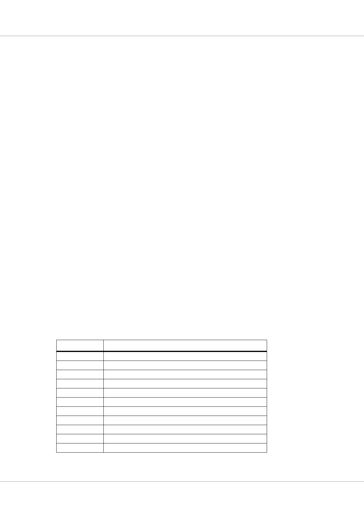
The cores connected to the clock gating unit are defined in the table below:
Table 429.Clocks controlled by CLKGATE unit
Bit Functional module
0 GRETH 10/100/1000 Mbit Ethernet MAC 0
1 GRETH 10/100/1000 Mbit Ethernet MAC 1
2 SpaceWire router
3 PCI master/target controller
4 MIL-STD-1553B controller
5 CAN controller
6 LEON4 Statistics unit
7UART 0
8UART 1
9 SPI Controller
10 PROM/IO memory controller