GR740-UM-DS, Nov 2017, Version 1.7 438 www.cobham.com/gaisler
GR740
39 Electrical description
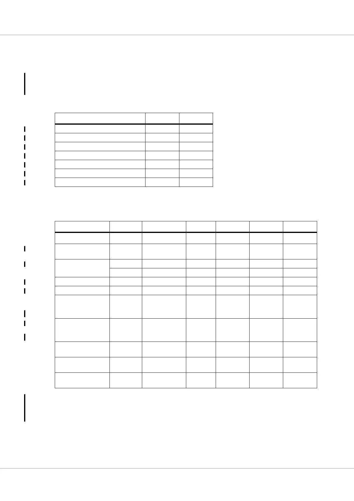
39.1 Absolute maximum ratings
Exceeding absolute maximum rating conditions might cause instantaneous or very short-term unre-
coverable hard failure (destructive breakdown). Stress from operating near absolute maximum levels
will affect long-term reliability of the device.
39.2 Recommended DC operating conditions
Table 574.Recommended DC operating conditions
1)
For SDRAM address/control/data and PCI data/control lines, V
IH OVERSHOOT
= 300 mV and V
IL UNDER-
SHOOT
= -300 mV with a maximum duration of 3 ns beyond the recommended limits can be tolerated per transi-
tion. Alternatively, if DC levels are limited to 3.4V then V
IH OVERSHOOT
= 500 mV and V
IL UNDERSHOOT
= -
500 mV with a maximum duration of 3 ns can be tolerated.
Table 573.Absolute maximum DC ratings
Parameter Abs Max Unit
VDD12 relative to GND 1.8 V
VDDPLLA relative to VSSPLLA 1.8 V
VDDPLLD relative to VSSPLLD 1.8 V
VDIG25 relative to VSS25 4.5 V
VDIG33 relative to VSS33 4.5 V
LVCMOS signals relative to VSS33 4.5 V
LVDS signals relative to VSS25 4.5 V
Parameter Symbol Conditions Minimum
Typical Maximum Unit
Temperature T
j
-40 25 125
°C
Digital core supply
voltage
VDD12 1.100 1.200 1.320 V
I/O bank supply VDIG25 2.200 2.500 2.750 V
VDIG33 3.000 3.300 3.600 V
Analog PLL supply VDDPLLA 1.100 1.200 1.320 V
Digital PLL supply VDDPLLD 1.100 1.200 1.320 V
HIGH (logic 1) level
input switching voltage
(LVCMOS)
1)
V
IH
2.0 3.3 3.6 V
LOW (logic 0) level
input switching voltage
(LVCMOS)
1)
V
IL
0.0 0.0 0.7 V
LVDS input common
mode voltage
V
ICM,LVDS
0.8 1.2 1.6 V
LVDS input differen-
tial
V
IDIFF,LVDS
0.100 0.200 0.400 V
LVDS output termina-
tion
R
O,LVDS
80 100 120 Ohm