GR740-UM-DS, Nov 2017, Version 1.7 390 www.cobham.com/gaisler
GR740
The debug mode can only be entered when the debug support unit is enabled through an external sig-
nal (DSU_EN). For DSU break (DSU_BREAK), and the break-now (BN) bit, to have effect the
Break-on-IU-watchpoint (BW) bit must be set in the DSU control register. This bit is set when
DSU_BREAK is active after reset and should also be set by debug monitor software when initializing
the DSU. When the debug mode is entered, the following actions are taken:
• PC and nPC are saved in temporary registers (accessible by the debug unit)
• an output signal (DSU_ACT) is asserted to indicate the debug state
• the timer units are (optionally) stopped to freeze the LEON timers and watchdog
The instruction that caused the processor to enter debug mode is not executed, and the processor state
is kept unmodified. Execution is resumed by clearing the BN bit in the DSU control register or by de-
asserting DSU_EN. The timer unit will be re-enabled and execution will continue from the saved PC
and nPC. Debug mode can also be entered after the processor has entered error mode, for instance
when an application has terminated and halted the processor. The error mode can be reset and the pro-
cessor restarted at any address.
When a processor is in the debug mode, an access to ASI diagnostic area is forwarded to the IU which
performs access with ASI equal to value in the DSU ASI register and address consisting of 20 LSB
bits of the original address.
33.3 AHB Trace Buffer
The AHB trace buffer consists of a circular buffer that stores AHB data transfers. The address, data
and various control signals of the AHB bus are stored and can be read out for later analysis. The trace
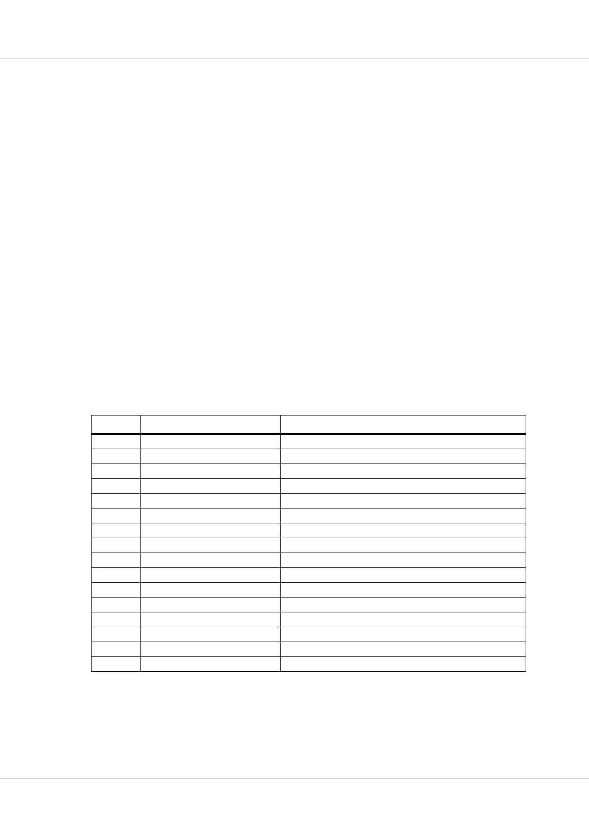
buffer is 224 bits wide. The information stored is indicated in the table below:
In addition to the AHB signals, the low part of the DSU time tag counter is also stored in the trace.
The trace buffer is enabled by setting the enable bit (EN) in the trace control register. Each AHB
transfer is then stored in the buffer in a circular manner. The address to which the next transfer is writ-
ten is held in the trace buffer index register, and is automatically incremented after each transfer. Trac-
ing is stopped when the EN bit is reset, or when a AHB breakpoint is hit. Tracing is temporarily
Table 519.AHB Trace buffer data allocation
Bits Name Definition
223:160 Load/Store data AHB HRDATA/HWDATA(127:64)
159:129 Load/Store data AHB HRDATA/HWDATA(63:32)
127 AHB breakpoint hit Set to ‘1’ if a DSU AHB breakpoint hit occurred.
126 - Not used
125:96 Time tag DSU time tag counter
95 - Not used
94:80 RESERVED RESERVED
79 Hwrite AHB HWRITE
78:77 Htrans AHB HTRANS
76:74 Hsize AHB HSIZE
73:71 Hburst AHB HBURST
70:67 Hmaster AHB HMASTER
66 Hmastlock AHB HMASTLOCK
65:64 Hresp AHB HRESP
63:32 Load/Store data AHB HRDATA/HWDATA(31:0)
31:0 Load/Store address AHB HADDR