GR740-UM-DS, Nov 2017, Version 1.7 431 www.cobham.com/gaisler
GR740
36.3 Registers
36.3.1 Register address map
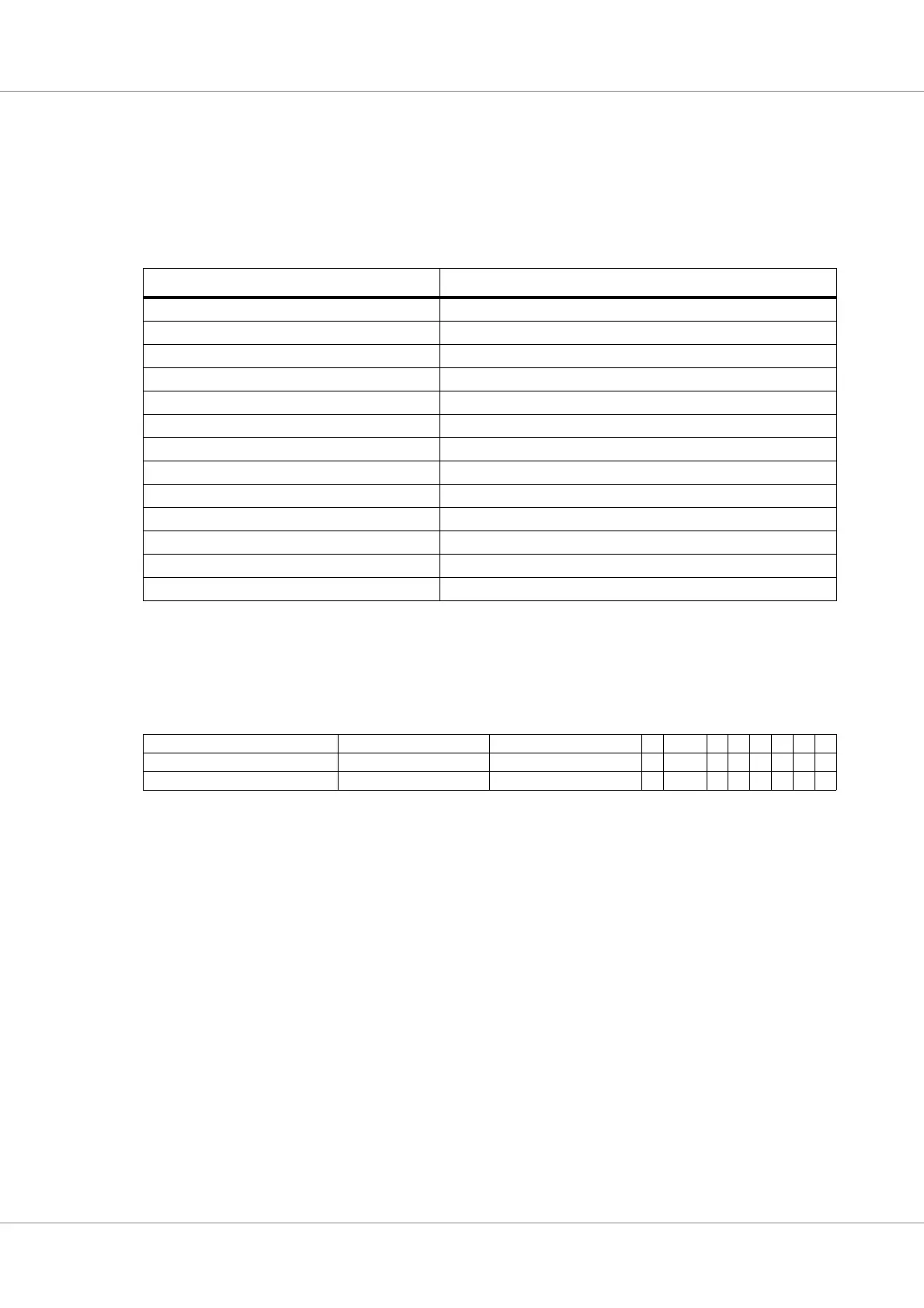
The trace buffer occupies 128 KiB of address space in the Debug bus AHB I/O area. The following
register address are decoded:
36.3.2 Trace buffer control register
The trace buffer is controlled by the trace buffer control register:
Table 566.Trace buffer address space
Address Register
0x000000 Trace buffer control register
0x000004 Trace buffer index register
0x000008 Time tag value
0x00000C Trace buffer master/slave filter register
0x000010 AHB break address 1
0x000014 AHB mask 1
0x000018 AHB break address 2
0x00001C AHB mask 2
0x010000 - 0x020000 Trace buffer
..0 Trace bits 127 - 96
...4 Trace bits 95 - 64
...8 Trace bits 63 - 32
...C Trace bits 31 - 0
Table 567.0x000000 - CTRL - Trace buffer control register
31 23 22 16 15 14 12 11 9 8 7 6 5 4 3 2 1 0
RESERVED DCNT RESERVED PF BW RF AF FR FW DM EN
0 0 0 0 0b00 00000*
r rw r rw r rwrwrwrw r rw
31: 23 RESERVED
22: 16 Trace buffer delay counter (DCNT) - Specifies the number of lines that should be written in the trace
buffer befiore entering debug mode after a AHB break/watchpoint has been hit.
15: 9 RESERVED
8 Performance counter Filter (PF) - If this bit is set to ‘1’, the cores performance counter (statistical)
outputs will be filtered using the same filter settings as used for the trace buffer. If a filter inhibits a
write to the trace buffer, setting this bit to ‘1’ will cause the same filter setting to inhibit the pulse on
the statistical output, which is connected to the LEON4 statisics unit. The filter settings are con-
trolled by fields AF, FT and FW (bits 4:2) below.
7: 6 Bus width (BW) - Read-only register with value "00" indicating a bus width of 32 bits.
5 Retry filter (RF) - If this bit is set to ‘1’, AHB retry responses will not be included in the trace buffer.
4 Address Filter (AF) - If this bit is set to ‘1’, only the address range defined by AHB trace buffer
breakpoint 2’s address and mask will be included in the trace buffer.
3 Filter Reads (FR) - If this bit is set to ‘1’, read accesses will not be included in the trace buffer. This
bit can only be set of the core has been implemented with support for filtering.
2 Filter Writes (FW) - If this bit is set to ‘1’, write accesses will not be included in the trace buffer.
This bit can only be set of the core has been implemented with support for filtering.
1 Delay counter mode (DM) - Indicates that the trace buffer is in delay counter mode.
0 Trace enable (EN) - Enables the trace buffer
This field has reset value 1 if the BREAK signal is LOW and has reset value 0 otherwise.