GR740-UM-DS, Nov 2017, Version 1.7 329 www.cobham.com/gaisler
GR740
24.2.2 3-wire transmission protocol
The core can be configured to operate in 3-wire mode, where the controller uses a bidirectional
dataline instead of separate data lines for input and output data. In 3-wire mode the bus is thus a half-
duplex synchronous serial bus. Transmission starts when a master selects a slave through the slave’s
Slave Select (SPI_SLVSEL) signal and the clock line SPI_SCK transitions from its idle state. Only
the Master-Output-Slave-Input (SPI_MOSI) signal is used for data transfer in 3-wire mode. The
SPI_MISO signal is not used.
The direction of the first data transfer is determined by the value of the 3-wire Transfer Order (TTO)
field in the core’s Mode register. If TTO is ‘0’, data is first transferred from the master (through the
MOSI signal). After a word has been transferred, the slave uses the same data line to transfer a word
back to the master. If TTO is ‘1’ data is first transferred from the slave to the master. After a word has
been transferred, the master uses the MOSI line to transfer a word back to the slave.
The data line transitions depending on the clock polarity and clock phase in the same manner as in SPI
mode. The aforementioned slave delay of the SPI_MISO signal in SPI mode will affect the SPI_-
MOSI signal in 3-wire mode, when the core operates as a slave.
24.2.3 Receive and transmit queues
The core’s transmit queue consists of the transmit register and the transmit FIFO. The receive queue
consists of the receive register and the receive FIFO. The total number of words that can exist in each
queue is thus the FIFO depth plus one. When the core has one or more free slots in the transmit queue
it will assert the Not full (NF) bit in the event register. Software may only write to the transmit register
when this bit is asserted. When the core has received a word, as defined by word length (LEN) in the
Mode register, it will place the data in the receive queue. When the receive queue has one or more ele-
ments stored the Event register bit Not empty (NE) will be asserted. The receive register will only
contain valid data if the Not empty bit is asserted and software should not access the receive register
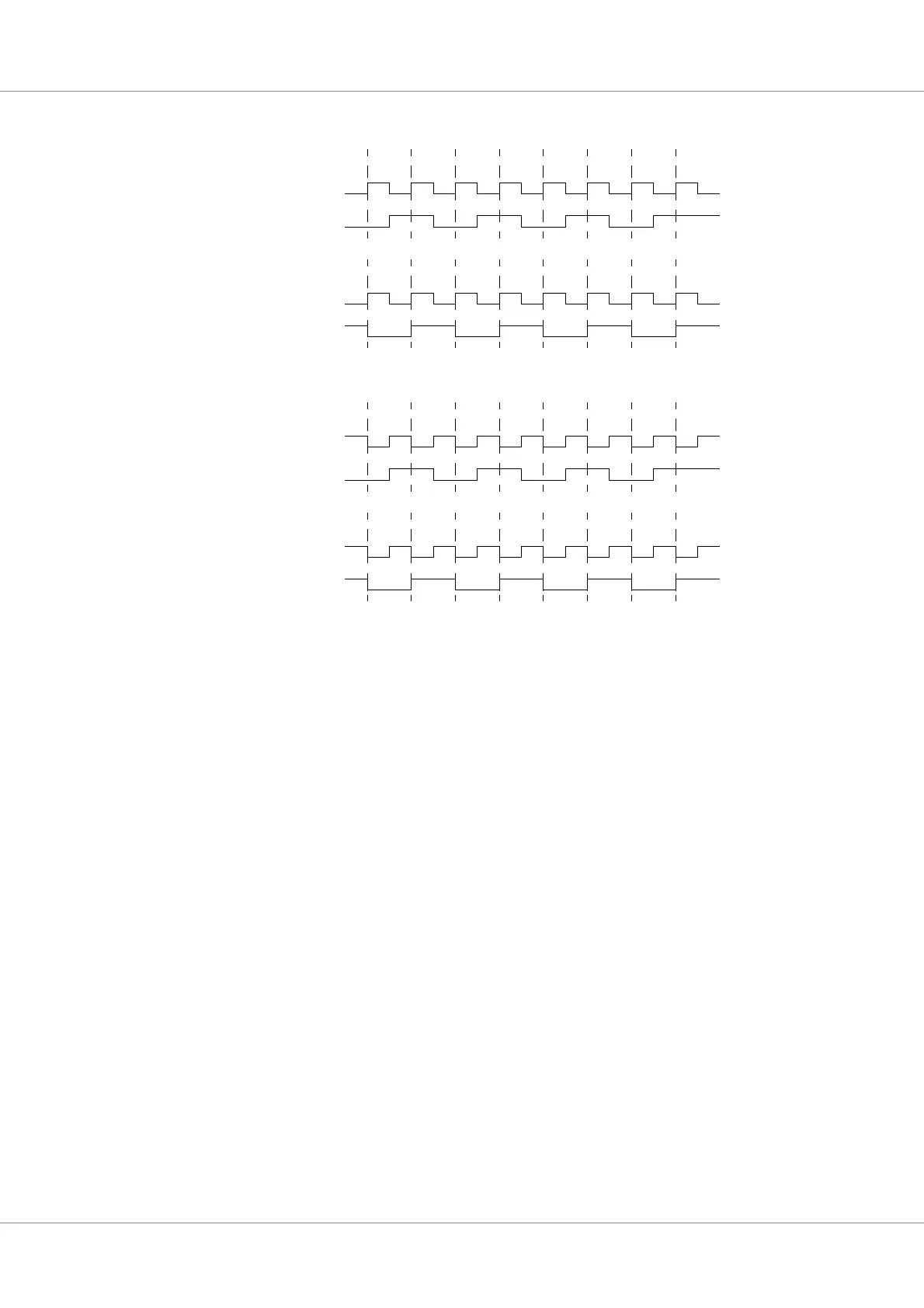
Figure 42. SPI transfer of byte 0x55 in all modes
SCK
MOSI
CPOL = 0
CPHA = 0
CPHA = 1
CPOL = 1
CPHA = 0
CPHA = 1
Mode 0
Mode 1
Mode 2
Mode 3
SCK
MOSI
SCK
MOSI
SCK
MOSI