Isolating Failing DIMMs E-5
4.
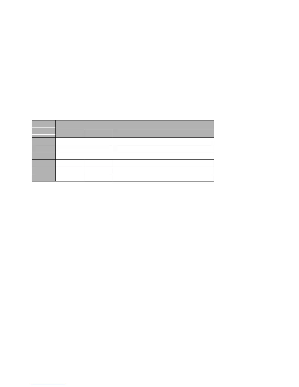
Use the following table to determine the proper set. Bits<27,28,29,30,31,32>
are from the failing address.
Configuration Type Bits <7:4> from DPR
Array
Size
4 & 5 9 D & F
256MB Lower Set Upper Set Bit <27> == 0 – Lower Set, 1– Upper Set
512MB Lower Set Upper Set Bit <28> == 0 – Lower Set, 1– Upper Set
1GB Lower Set Upper Set Bit <29> == 0 – Lower Set, 1– Upper Set
2GB Lower Set Upper Set Bit <30> == 0 – Lower Set, 1– Upper Set
4GB Lower Set Upper Set Bit <31> == 0 – Lower Set, 1– Upper Set
8GB Lower Set Upper Set Bit <32> == 0 – Lower Set, 1– Upper Set
5.
Now that you have the real array, the failing Data/Check bits, and the
correct set, use Table E–4 to find the failing DIMM or DIMMs.
The table shows data bits 0–255 and check bits 0–31. These data bits indicate a
single-bit error. An SROM compare error would yield address and data bits
from 0–63. When you convert the address to be in the correct range, the failing
data would be somewhere between 0 and 255.
Continued on next page