CONTROLS
10
The following pages contain information which will help you become more familiar with the dif -
ferent gauges and controls used while operating this vehicle.
Figure 7
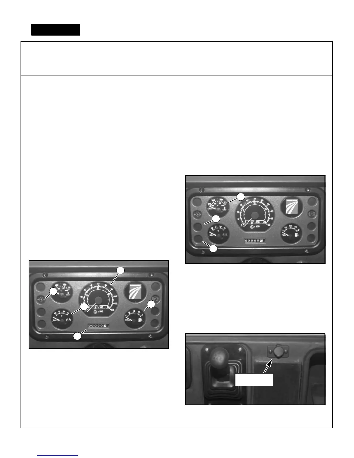
Dash Panel Identification
OIL PRESSURE WARNING LIGHT (4)
The red oil pressure light (See Fig. 6) indicates oil pres-
sure is too low for engine operation.
WATER TEMPERATURE GAUGE, AND
OVERHEAT WARNING BUZZER
(7)
GAUGES, WARNING LIGHTS and CONTROLS
Figure 6
Dash Panel Identification
The purpose of this system is to warn the operator if the
engine temperature exceeds the normal operating
range.
VOLTMETER (5)
The voltmeter (See Fig. 6) indicates the voltage level of
the battery. Under normal operation it will indicate 12 to
18 volts (meaning the battery is being properly
charged). A reading below 12 volts indicates the bat-
tery is being drained, this may indicate a malfunction
in the charging system which should be checked
immediately.
TACHOMETER (1)
Indicates the engine speed (x 100) in revolutions per
minute(SeeFig.6).
FUEL GAUGE (3)
The fuel gauge (See Fig. 6) indicates the amount of fuel
remaining in the fuel tank.
7
If the water temperature gauge (See Fig. 7) raises above
the 230E F(110EC mark), a heat sensor is activated
causing the overheat warning buzzer to sound.
HOUR METER (2)
The hour meter (See Fig. 6) records the number of
hours the engine has run. The hour meter runs when the
key switch is “ON” even if the engine is not running.
BRAKE FLUID LEVEL WARNING LIGHT (6)
This light (See Fig. 7) indicates the brake fluid level is
low.
6
Figure 8
Accessory Power Plug
ACCESSORY POWER PLUG
A power port is available for plugging in laptop comput-
ers, cellular phones and other accessory items which
require a 12-volt plug-in (See Fig. 8).
Accessory
Power Plug
3
1
2
4
GLOW PLUG INDICATOR (8)
(DIESEL ONLY)
The glow plugs must be preheated before the engine
can be started. The glow plug indicator is wired in the
glow plug circuit and indicates when the glow plugs are
being heated and when the engine is ready to start (See
Fig. 7).
5
8