SERVICE & MAINTENANCE Cont.
30
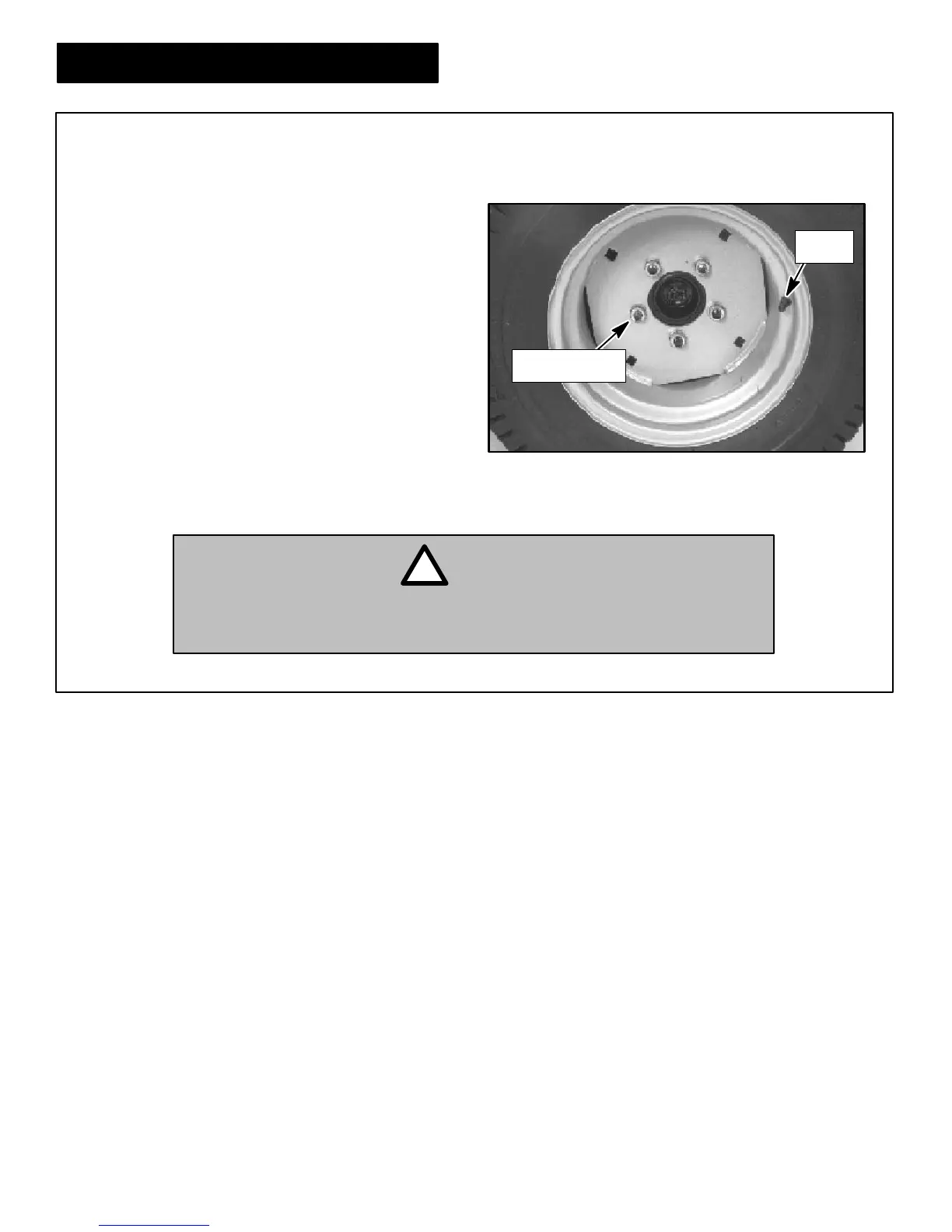
TIRE REMOVAL
Front & Rear
1. Remove the wheel retaining nuts (See Fig 36) and
remove tire and wheel assembly from hub.
2. Install the tire and wheel by reversing the above
sequence. Make sure valve stem (See Fig 36) is
located toward the outside.
3. T ighten wheel retaining nuts to 70 to 100 ft. lbs.
(95 to 140 N·m) torque.
Figure 36
Wheel Retaining Nuts and Valve Stem
• DO NOT rely solely on hydraulic or mechanical jacks for support. Use
appropriate jack stands or equivalent for supporting the vehicle. Never
place feet, hands or any part of your body under the vehicle when raising it.
WARNING
!
With the vehicle on a flat level surface (if possible), put
the gear selector in first gear and apply the park brake.
Place a block in front of (or behind) the tire diagonally
opposite the side which is being raised (Refer to the
“Jacks, Jacking Locations and Using a Hoist” sec-
tion, Pages 26-27 in this manual).
Raise the vehicle only enough to perform the mainte-
nance required.
Wheel
Retaining Nuts
Valve
Stem