OPERATING REMOTE HYDRAULICS Cont.
49
• To engage P.T.O. ALWAYS STOP the vehicle. For
vehicles with manual transmissions, stop the
vehicle, push the clutch pedal in THEN pull the
P.T.O. control knob upward.
For Use While Vehicle Is Moving
For Use When The Vehicle Is Stationary
1. Make sure governor control is in “UP” position.
2. Set (engage) the parking brake.
3. Put transmission in neutral (out of gear) and engage
the clutch (put automatic transmission in Park).
4. Push foot throttle pedal to floorboard.
5. Raise the hand throttle control lever to full engine
R.P.M.
NOTICE
Power Take Off (Hydraulic P.T.O.) con’t.
WARNING
!
• If you do not want the vehicle to move, ALWAYS make sure the transmission is out of
gear and the park brake is applied when the clutch pedal is released to activate the
P.T.O. shaft. Make sure the vehicle is in Park with the park brake applied for automatic
transmissions.
• AL WAYS disengage the P.T.O. before attaching any equipment to the P.T.O. shaft.
AL WAYS remain clear of the P.T.O. shaft and all moving parts.
1. Refer to the Power Take-Off R.P.M./Vehicle Speed chart (see Page 50) to select the proper P.T.O. and ground
speed combination for the accessory equipment being used, there is also a decal representing the P.T.O. and
ground speed combinations located on the same panel as the P.T.O. control handle.
2. Position the governor control lever to obtain engine R.P.M. corresponding to the desired P.T.O. and vehicle
ground speed.
3. Put transmission in desired gear , engage clutch (for vehicles with manual transmissions) and depress foot
throttle.
4. Pull up on the hydraulic P.T.O. control handle to start P.T.O. operation. The P.T.O. can only be stopped by
pushing the control handle down.
WARNING
!
• NEVER attempt to drive the vehicle with the engine speed increased by the hand
throttle. The hand throttle also controls the foot th rottle, so the foot th rottle pedal
cannot be used to reduce engine and vehicle speed. F AILURE to obey this warning
may result in you, the operator, losing vehicle contro l.
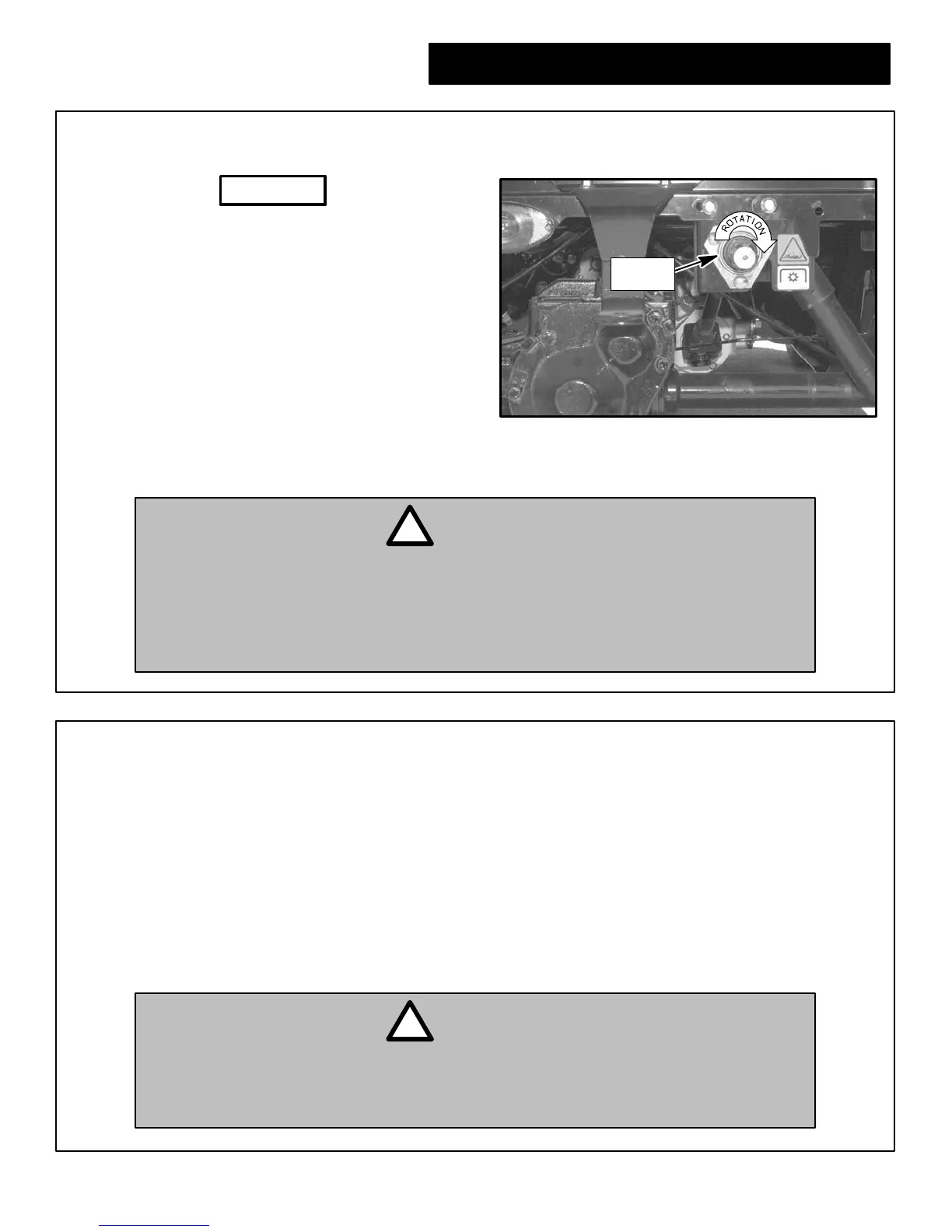
P.T. O .
Shaft
Figure 73
P.T.O. Shaft Location
6. Move the governor control lever to desired engine R.P.M.