EasyManuals Logo

CYG PRS-7367 User Manual

CYG PRS-7367
360 pages
To Next Page IconTo Next Page
To Previous Page IconTo Previous Page
Page #104 background imageLoading...
Page #104 background image
Protection Functions
96 PRS-7367
3.15.2.1 Initiation logic
&
27_Ena=1
SET
10V < Ua < 27_Vol_Str
ANA
ANA
ANA
10V < Ub < 27_Vol_Str
10V < Uc < 27_Vol_Str
27_Str_Ph
_Num
27_Vol_Select = 1
SET
&
ANA
ANA
ANA
20V < Ubc < 27_Vol_Str
20V < Uca < 27_Vol_Str
27_Str_Ph
_Num
&

1
20V < Uab < 27_Vol_Str
SIG
27_Blk=1
Initiation
FLG
Max(Ia, Ib, Ic) < 27_Cur_Blk
ANA
1
27_Vol_Select = 2
SET
27_Cur_Blk_Ena = 1
SET
Duadt > 27_Dudt_Blk
ANA
27_Dudt_Blk_Ena = 1
SET
Dubdt > 27_Dudt_Blk
ANA
Ducdt > 27_Dudt_Blk
ANA
1
&
&
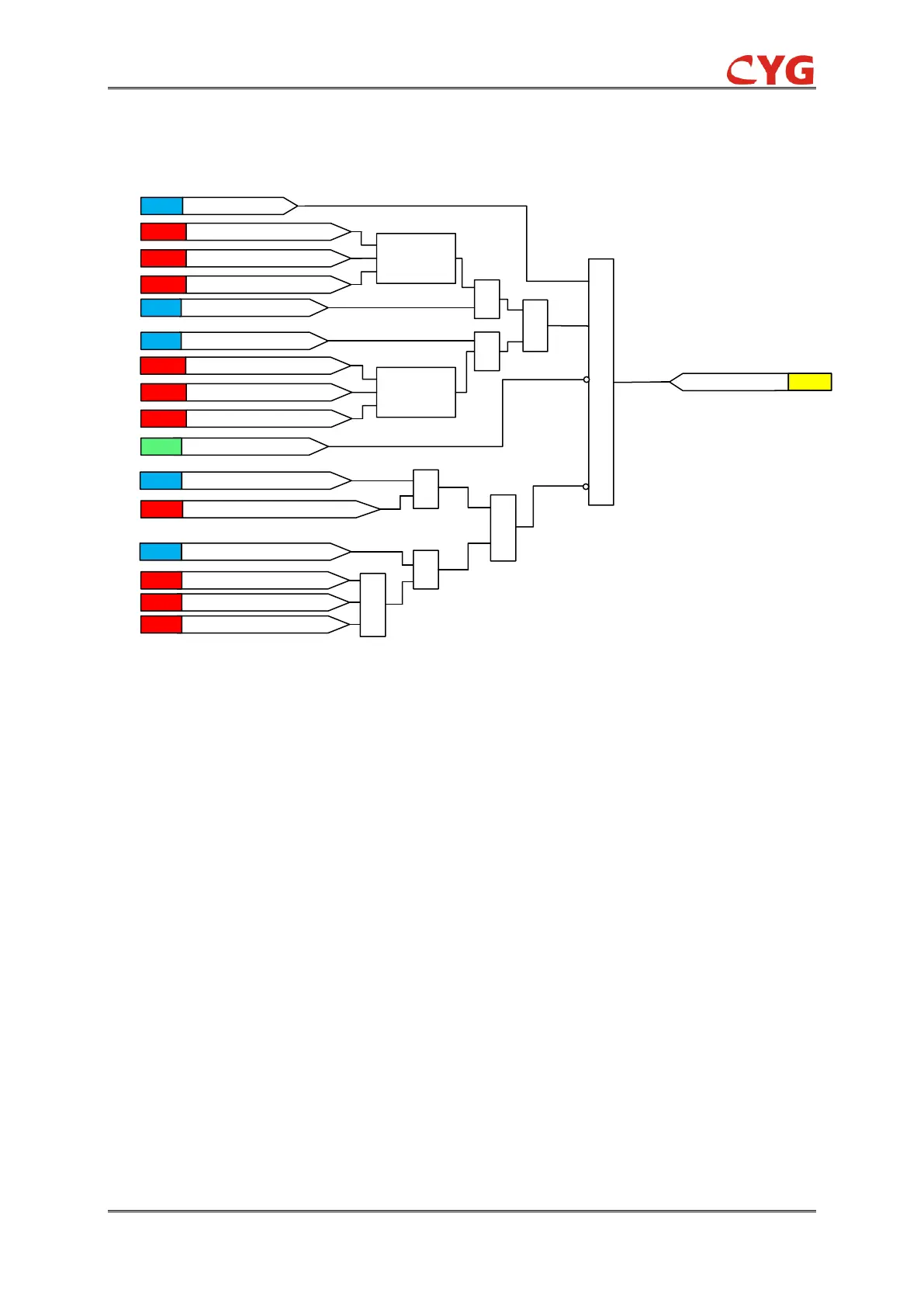
Figure 3.15-2 The initial diagram
The protection can be blocked by low current, it can be enabled or disabled by setting
27_i_Cur_Blk_Ena, when 27_i_Cur_Blk_Ena=1 and the maximum phase current is less than the
setting 27_i_Cur_Blk, the relay is blocked.
The protection can be blocked by the rate of voltage change, it can be enabled or disabled by
setting 27_i_Dudt_Blk_Ena, when the 27_i_Dudt_Blk_Ena=1 and the du/dt is larger than setting
27_i_Dudt_Blk.
When the relay is enabled, the fundamental frequency component of the measured three phase
voltages and currents are compared phase-wise to the set Start value. If the three phase voltages
are lower than the set value of the voltage, the relay will initial.
3.15.2.2 Timer element
The functional module diagram is shown as below:

Table of Contents

Questions and Answers:

Question and Answer IconNeed help?

Do you have a question about the CYG PRS-7367 and is the answer not in the manual?

CYG PRS-7367 Specifications

General IconGeneral
BrandCYG
ModelPRS-7367
CategoryControl Unit
LanguageEnglish