3.29.2 32R Protection Principle
The reverse power protection function can be enabled or disabled by setting the corresponding
32R_Ena parameter values as "1" or "0".
The operation of the reverse power protection can be described by using a module diagram. All
the modules in the diagram are explained in the next sections.
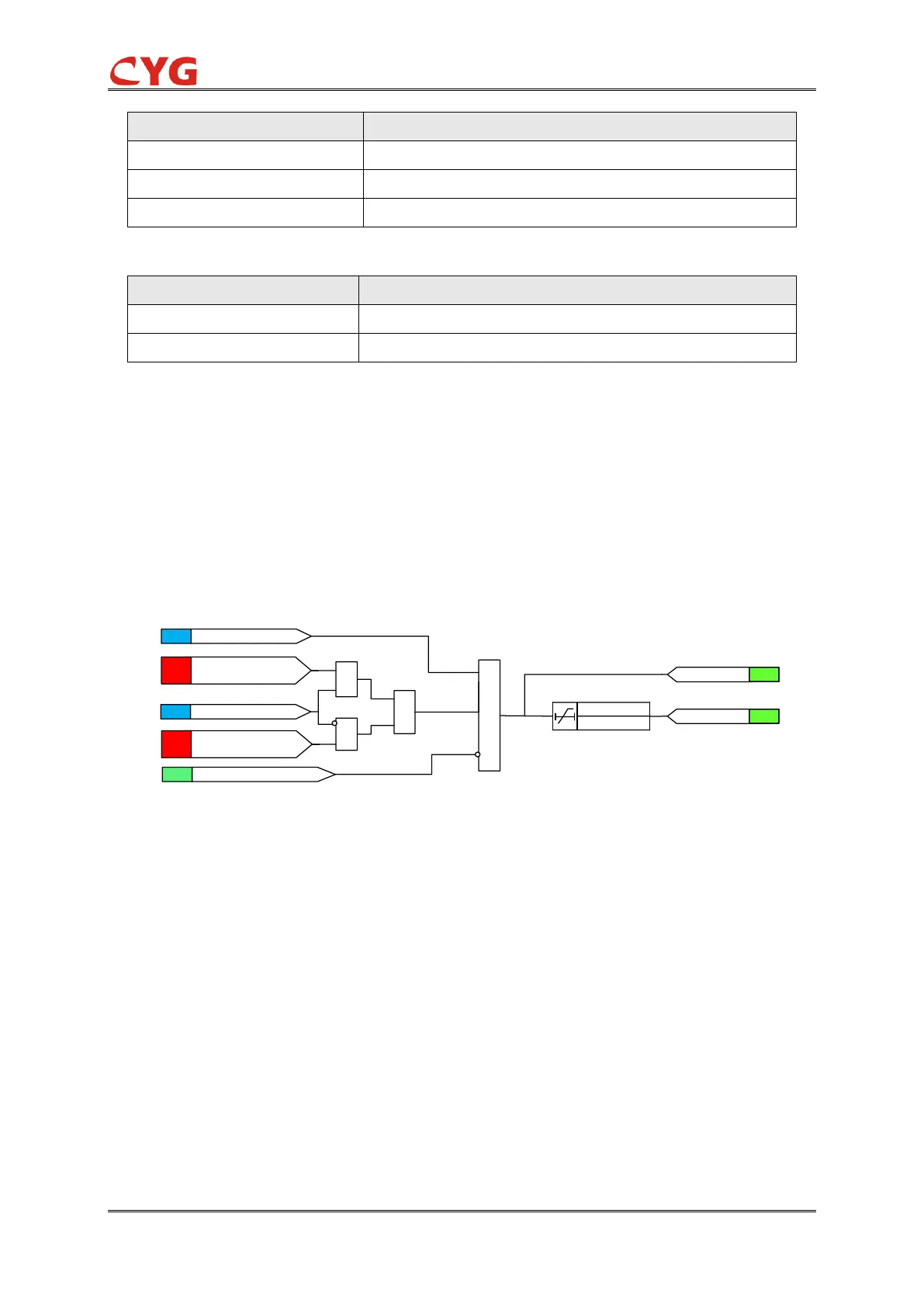
The two-step protection logic is almost the same except for the individual settings, the functional
module diagram of step 1 is shown as below:
Figure 3.29-2 Functional module diagram
The power value is compared to the startup value setting. If the 32R_Dir is 1, the power value
exceeds the setting 32R_Pwr_Str, and if the 32R_Dir is 0, and the power value is less than the
negative setting; And then if there is no block signal is activated, the timer and 32R_Str signal are
activated.
Where:
32R_Ena can enable PWR 32R protection;
32R_StrVal is the power startup setting;
32R_StrAng is the power startup angle setting;
32R_Op_T is the operate time setting;
32R_Dir can switch the operation mode. 32R_Dir = 1 is recommended, which means the
system is operating in forward mode. On the contrary, 32R_Dir = 0 means the system is
operating in reverse mode.