Monitoring & Control
PRS-7367 261
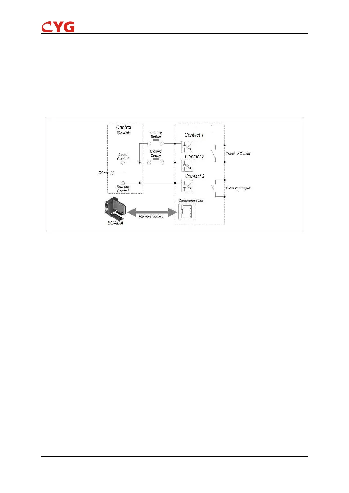
remote control command can be remotely dispatched through the network communication like
IEC61850 or DNP. Before executing a remote control command, it is necessary to turn the
Local/Remote control switch to the “Remote” position.
The output relays in the BO module can be configured as output contacts so as to close or trip the
apparatus. Each control output can be control with an interlock module (which can be configured
through the PRS IED Studio) if the corresponding interlock logic setting (see Section 7.4.3) is set
to activation.
Figure 5.7-1 Demonstration Diagram of The Control Function
5.8 Signaling
All inputs of the protection hardware unit are configurable via PRS IED Studio software. Common
binary inputs can be configured for the following purposes:
Bay primary equipment state acquisition, such as circuit breaker position, insulator position.
These signals can be sent to the substation monitoring system or dispatching automation
system through the protection device.
Used for BI condition of the protection logic to achieve the block or release of inner logic.
Used to monitor the health condition of primary equipment such as SF6 low pressure alarm
and transformer high oil temperature. These signals can be used as function input of
protection logic, and also can be sent to substation monitoring system or dispatching
automation system as separate alarm signals. Achieve remote monitoring.
Transformer tap position input
All hardware input denouncing time can be set separately. Denouncing time setting can be done
through the LCD or PRS IED Studio software.


 To Next Page