Protection Functions
PRS-7367 53
The Stage i Curve parameter B
The Stage i Curve parameter C
The Stage i Curve parameter P
The Stage i Curve parameter k
The Stage i Minimum Operating
time for IDMT
The Stage i Reset delay time
The Stage i Operation
Enable/Disable
The Stage i Alarm Enable/Disable
The Stage i measured residual
current/calculated residual current
3.5 Directional earth-fault protection 67G
3.5.1 67G Overview
This relay provides four stages of directional earth-fault overcurrent protections with independent
definite time and inverse definite minimum time characteristics. Each stage can be enabled or
disabled independently by the corresponding logic setting respectively.
When this relay is used in small resistance grounding system, the grounding zero sequence
current during earth fault is larger and can be used for tripping directly. All stages are equipped for
the zero sequence overcurrent protection. In this case, the zero sequence current for tripping can
be calculated or directly derived from a zero sequence current transformer.
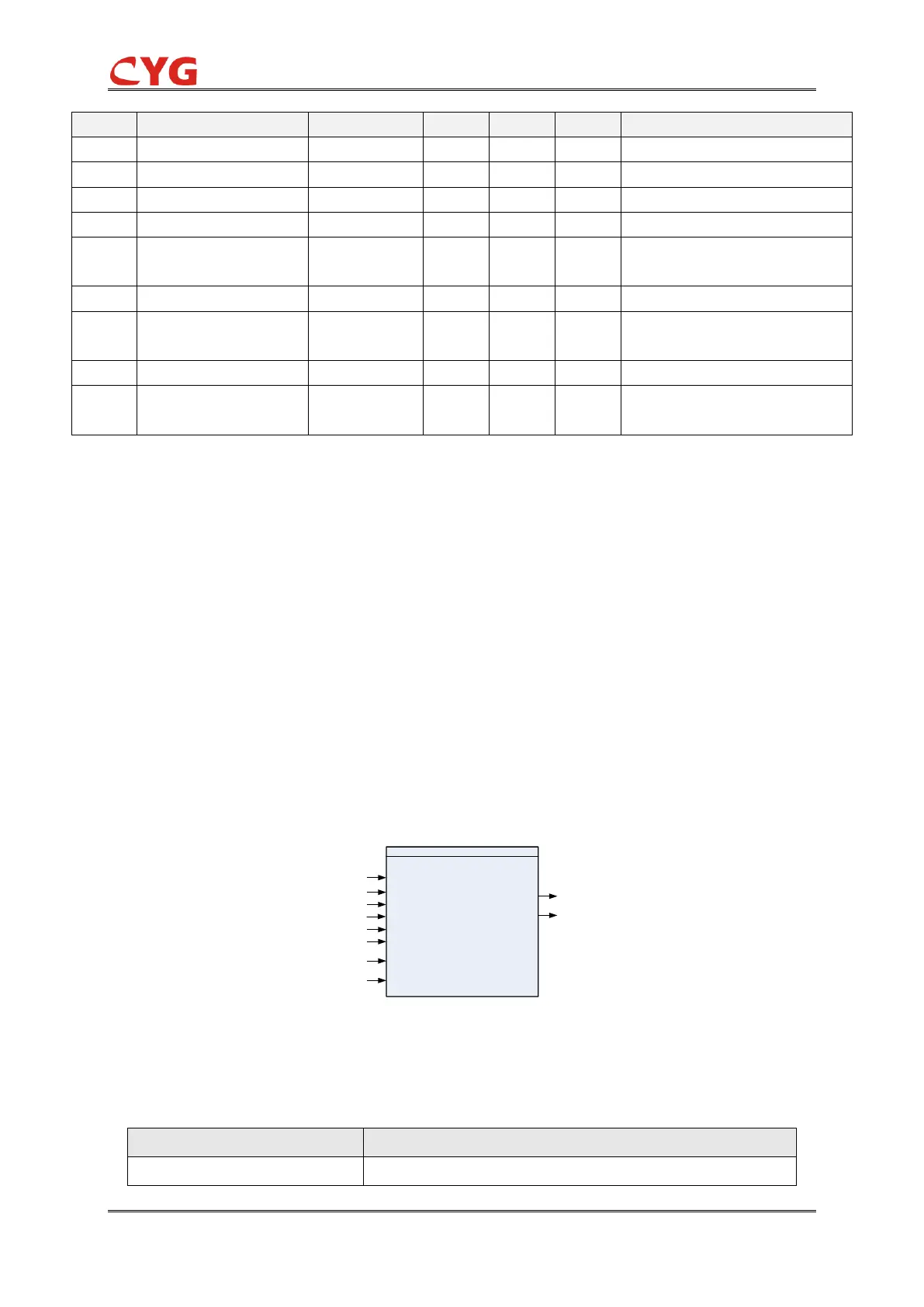
3.5.1.1 Function Block
The function block of the protection is as below.
OCTG_67G
Blk
Blk_Str
Blk_Op
Str
Op
Ena_Mult
U3P
I3P
PTSAlm
CTSAlm
Figure 3.5-1 Function block
3.5.1.2 Signals
Table 3.5-1 Input Signals
The voltage in all the three phases