Protection Functions
PRS-7367 155
3.30.1.2 Signals
Table 3.30-1 Input Signals
The voltage magnitude in all the three phases
The current magnitude in all the three phases
This signal blocks all the binary output signals of the function
Table 3.30-2 Output Signals
This is the integrated start signal
This is the integrated operation signal.
3.30.2 32 Protection Principle
The power protection function can be enabled or disabled by setting the corresponding 32_Ena
parameter values as "1" or "0".
The operation of the power protection can be described by using a module diagram. All the
modules in the diagram are explained in the next sections.
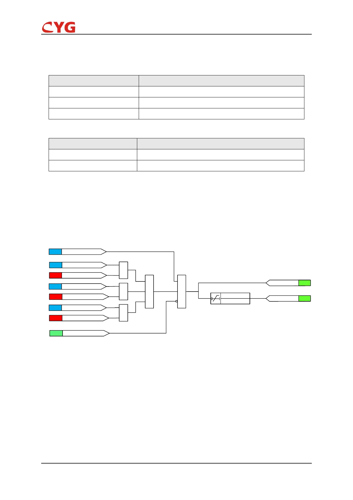
The functional module diagram is shown as below:
&
1
P>32_Pwr_Str
ANA
P<32_Pwr_Str
ANA
P<-32_Pwr_Str
ANA
SET
32_Dir=1
SIG
32_Block=1
&
&
SET
32_Dir=2
SET
32_Dir=0
&
SET
32_Ena=1
20ms
32_Op_T
32_Str
SIG
32_Op
SIG
Figure 3.30-2 Functional module diagram
The power value is compared to the startup value setting. If the 32_Dir=1, it is over power, the
power value exceeds the setting 32_Pwr_Str; and if the 32_Dir =2, it is under power, and the
power value is less than the setting 32_Pwr_Str; and if the 32_Dir =0, it is reverse power, and the
power value is less than the negative setting -32_Pwr_Str; And then if there is no block signal is
activated, the timer and 32_Str signal are activated.
Where:
32_Ena can enable or disable the 32 protection;
32_StrVal is the power startup setting;

 Loading...