Protection Functions
142 PRS-7367
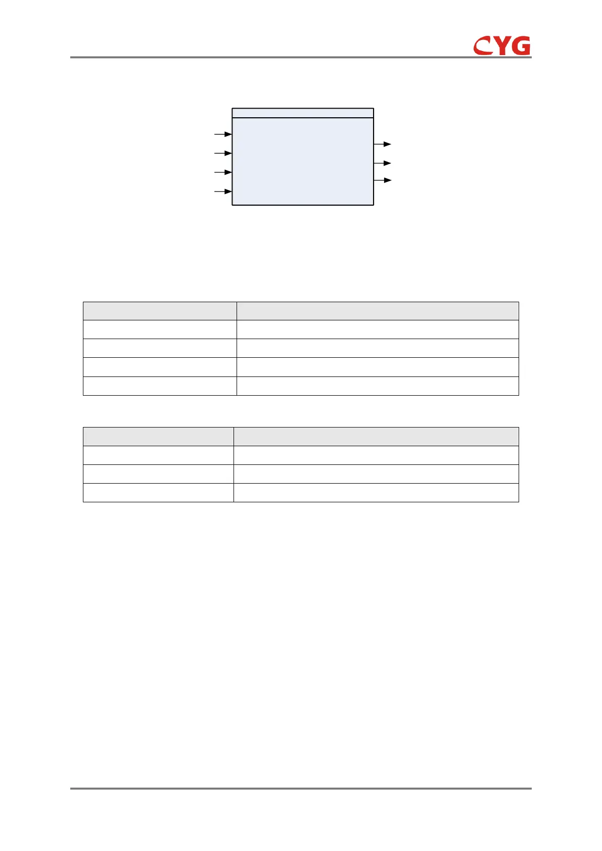
3.26.1.1 Function Block
U3P
59NA
Blk
BlkStr
BlkOp
Str
Op
Alm
Figure 3.26-1 The function block
3.26.1.2 Signals
Table 3.26-1 Input Signals
The voltage magnitude in all the three phases
This signal blocks all the binary output signals of the function
This signal blocks all the start outputs of the function
This signal blocks all the trip signals of the function.
Table 3.26-2 Output Signals
This is the integrated start signal.
This is the integrated operation signal.
This is the integrated alarm signal.
3.26.2 59NA Protection Principle
A standard Double-Y-connected shunt capacitor bank configuration is shown in following diagram.
The fundamental frequency component of an unbalance voltage is measured on the common
neutral connecting the two balanced parts of a shunt capacitor bank.