Protection Functions
104 PRS-7367
Table 3.18-1 Input Signals
The voltage magnitude in all the three phases
This signal blocks all the binary output signals of the function
Table 3.18-2 Output Signals
This is the integrated start signal.
This is the integrated operation signal.
3.18.2 81O Protection Principle
The over frequency protection function can be enabled or disabled by setting the corresponding
81O_Ena parameter values as "1" or "0".
The operation of the over frequency protection can be described by using a module diagram. All
the modules in the diagram are explained in the next sections.
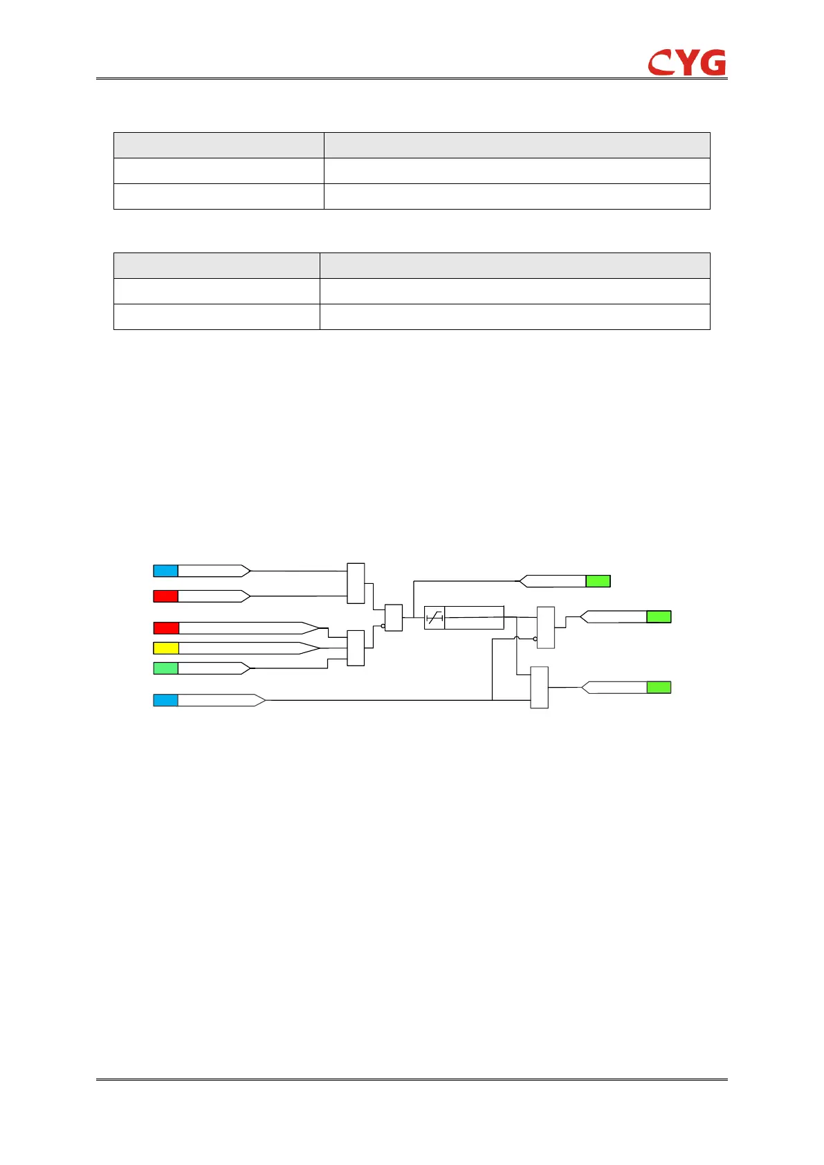
The two-step protection logic is almost the same except for the individual settings, the functional
module diagram of step 1 is shown as below:
1
&
81O_Op
&
SIG
ANA
f>[81O_Fr_Str]
SIG
81O_Str
81O_Ena=1
ANA
MinUpp<[81O_Vol_Blk]
SET
81O_Blk=1
SIG
30ms
81O_Op_T
FLG
f>(fn+20)Hz or f<(fn-20)Hz
& 81O_Alm
SIG
81O_Alm_Ena=1
SET
&
Figure 3.18-2 Functional module diagram
The fundamental frequency of the voltage is compared to the start value setting. If the frequency
exceeds the set 81O_Fr_Str and no block signal is activated, the timer and 81O_Str signal are
activated. However, if the voltage magnitude is below the 81O_Vol_Blk set value or the difference
between the measured frequency and the rated frequency exceeds 20 Hz, the timer and 81O_Str
signal are deactivated.
Where:
81O_Fr_Str is the Frequency setting of the 81O.
81O_Op_T is the operate time setting of the 81O.
The time characteristic is according to DT. When the operation timer has reached the value set by
81O_Op_T, the OPERATE output is activated. If the frequency becomes normal before the
module operates, the operation resets after 30ms.