Monitoring & Control
PRS-7367 249
conditions. If the conditions do not persist for the specified time, the procedure is restarted until the
conditions are fulfilled again. The circuit breaker closing is thus not permitted until the Close
Loop situation has remained constant throughout the set delay time [SetSN_Sync_RESETIME].
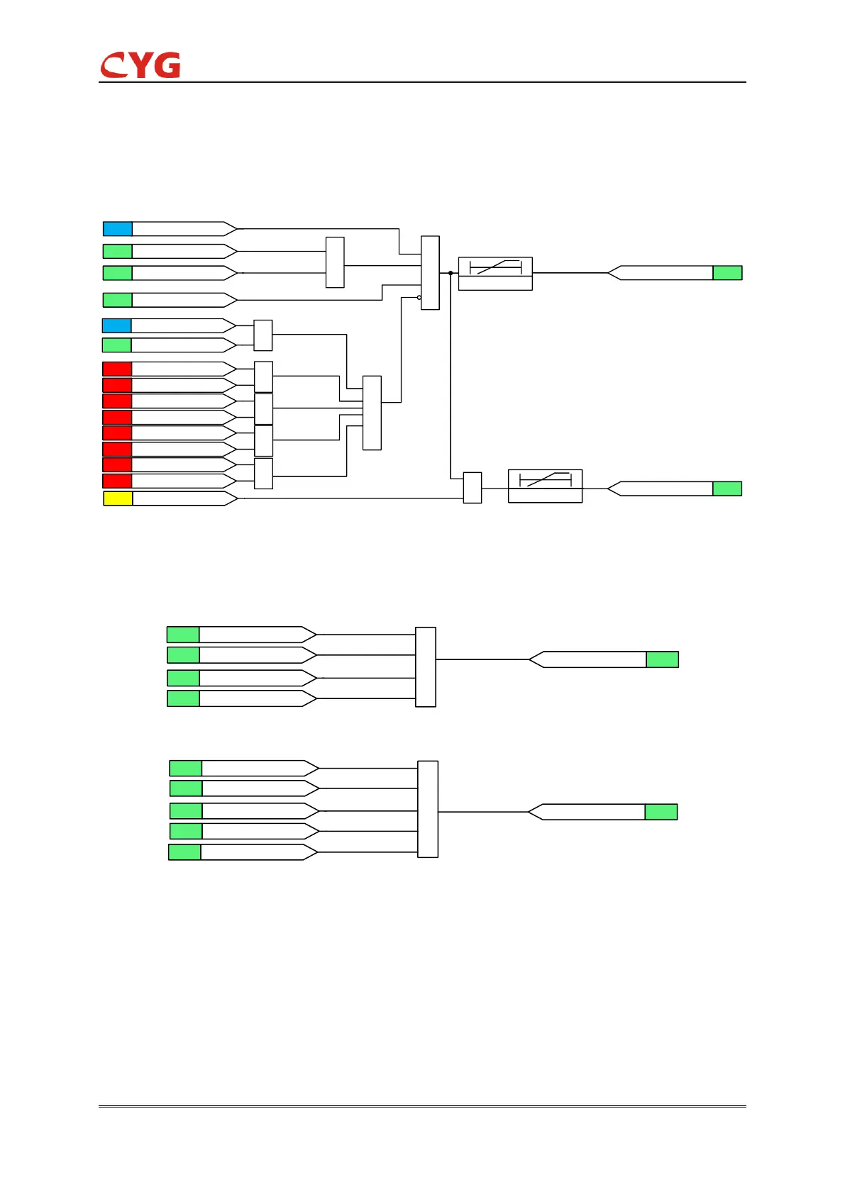
The logic diagram of Close Loop is shown as below:
&
&
SIG |Usys-Ulin| < Sync_DU
SIG
|Asys-Alin| < Sync_DA
25SYNC_CLSLOOPSET
SIG25SYN_CLSLOOP_OK
Uref > 25SYN_OVANA
Uref < 25SYN_UVANA
Usyn > 25SYN_OVANA
Usyn < 25SYN_UVANA
Fref > 25SYN_OFANA
Fref < 25SYN_UFANA
Fsyn > 25SYN_OFANA
Fsyn < 25SYN_UFANA
1
1
1
1
1
SIG
|Fsys-Flin| < Sync_SameFr
25SYN_T_LOOP / 0
SIG25SYN_CLSLOOP_OUT
&
25SYN_T_LOOP / 0
SIG 25SYN_Sync_BSFlg
FLG
25SYN_START
25SYNC_FORBID_LOOPSET
&
Figure 5.2.2-3 Logic diagram of the Close Loop function
5.2.3 25SYN Check Result
If the result of any check mode is right, synchro check result is right.
1
SIG 25SYN_ENERGCHK_OUT
SIG
25SYN_SYNCHK_OUT
SIG25SYN_Synchrocheck_OUT
SIG
25SYN_CLSLOOP_OUT
SIG 25SYN_NOCHK_OUT
Figure 5.2.3-1 Logic diagram of the Synchrocheck_OUT
1
SIG 25SYN_DL_LB_OK
SIG
25SYN_LL_DB_OK
SIG25SYN_Synchrocheck_OK
SIG
25SYN_SYNCHK_OK
SIG
25SYN_DL_DB_OK
SIG
25SYN_CLSLOOP_OK
Figure 5.2-2 Logic diagram of the Synchrocheck_OK
NOTICE!
During the Energy Check or Close Loop, there is a special case that must be considered. If
the synchronization period is stated (Time period is SetSN_Sync_RESETIME), and the result is not
satisfied in the time from Treset to T1. The condition is OK at the time of T1, but the remaining
time T1 is less than the exit delay time(SetSN_Sync_TDelay). In this case, when the time of T1 is
over, the device will stop the exit logic and the synchro check is failure.