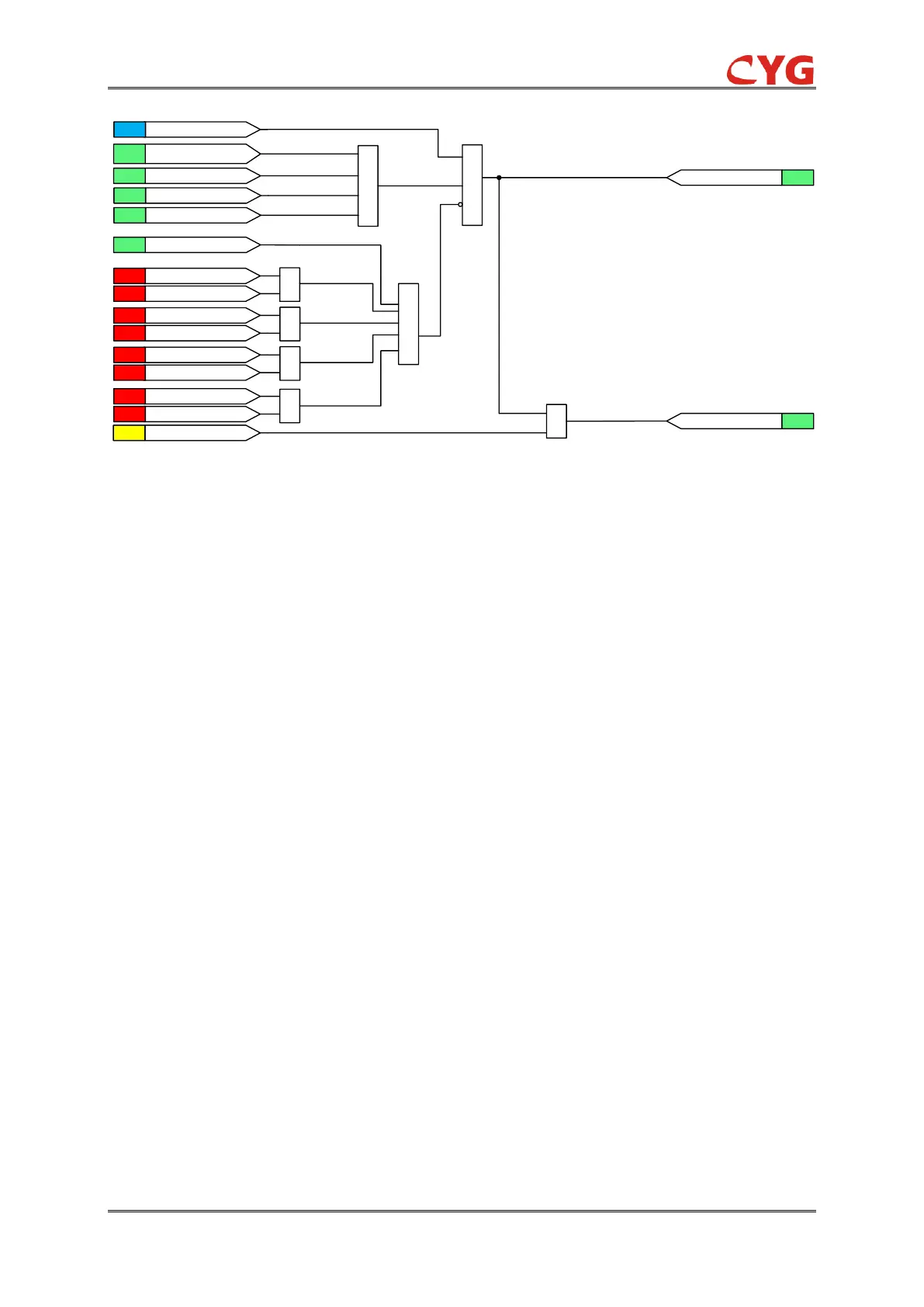
Figure 5.2.2-2 Logic diagram of the Check Sync function
Close Loop
The Close Loop module is used for the controlled closing of a circuit breaker in an
interconnected network. When used, the function gives an enabling signal at satisfying voltage,
frequency and phase angle conditions across the breaker to be closed. The function can be used
as a condition to be fulfilled before the breaker is closed.
The Close Loop module measures the amplitude, frequency and phase angle of the voltages on
both sides of a circuit breaker and compares them to the threshold value of the limit detectors. The
differences in voltage, frequency and phase angle values between the two sides of the circuit
breaker are measured and available for evaluation before the synchronizing is done. If the
available bus voltage is phase-to-phase and the line voltage is phase-to-neutral (or the opposite),
a compensation is required. This is done with the voltage ratio, which scales up the line voltage to
a level equal to the bus voltage. A typical example is to compensate for the voltage difference
caused by connecting the bus voltage as phase-to-phase and the line voltage as phase-to-neutral,
in which case the value of the voltage ratio is 1.732.
The Close Loop module starts the synchronizing check if the voltage at both sides of the
breaker is above the set value of SetSN_Sync_SynUV and not exceed the overvoltage threshold
SetSN_Sync_SynOV and the frequency at both sides of the breaker is above the set value of
SetSN_Sync_SynUF and not exceed the overfrequency threshold SetSN_Sync_SynOF. When the
values of the voltages and frequencies on both sides are fulfilled, the measured values are
compared to the set value for phase angle and voltage difference, which are set using
SetSN_Sync_DA and SetSN_Sync_DU settings. If a compensation factor is set due to the use of
different voltages on the bus and line, the factor is deducted from the line voltage before the
comparison is made for the phase angle values.
The frequency on both sides of the circuit breaker is also measured. It is also required that the
difference in frequencies on both sides of the breaker must be below 0.05Hz.
The CLSLOOP_OK output are activated when the actual measured conditions match the set
 Loading...