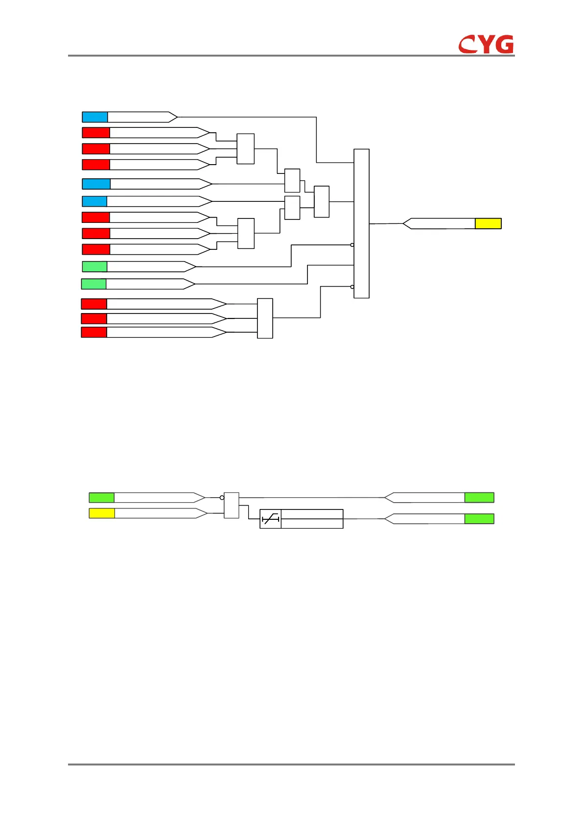
Figure 3.17-2 The initial diagram
When the relay is enabled, the fundamental frequency component of the measured three phase
voltages and currents are compared phase-wise to the set Start value. If the three phase voltages
are lower than the set value of the voltage, the relay will initial.
3.17.2.2 Timer element
The functional module diagram is shown as below:
Figure 3.17-3 Timer element
If the initiation condition is satisfied and no block signal is activated, the CUB_27_Str signal is
activated.
The time characteristic is according to DT. When the operation timer has reached the value set by
CUB_27_Op_T, the CUB_27_Op is activated. Alm output is activated If the three phase voltages
normalize before the module operates, the operation resets with a time delay of 30ms.
3.17.3 CUB_27 Application Scope
CUB_27 relay is applied to capacitors. The capacitor may have residual voltage after cutting off
power. During restoring period, the capacitor may withstand overvoltage due to residual voltage,
which will damage the capacitor.