3.3.2 67P Protection Principle
Each stage of the protection function can be enabled or disabled by setting the corresponding
67P_Ena parameter values as "1" or "0".
The operation of directional overcurrent protection can be described using a module diagram. All
the modules in the diagram are explained in the next sections.
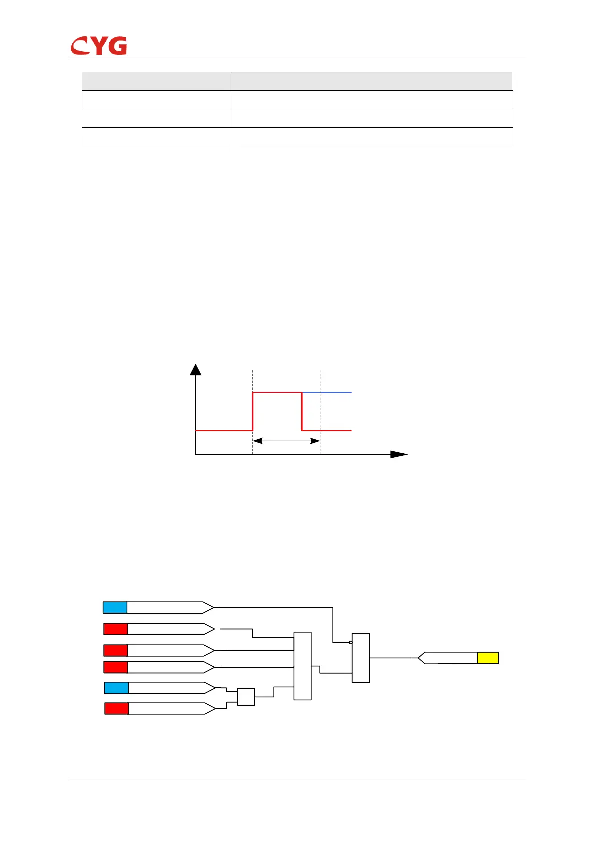
PTS Alarm Blocking of 67P
The PTS alarm can be set by PTS_Blk setting, if PTS_Blk=1 and the PTS Alm signal is 1, the 67P
function will be blocked, including the startup, trip and the timer will be reset; when if PTS_Blk=0
and the PTS Alm signal is 1, the VCE element and the Direction function will be valid, the 67P
function will become the Non directional overcurrent.
Figure 3.3-2 PTS Alarm Open and Block Condition
Voltage Control Element (VCE) of 67P
In this part of 67P, the Voltage Control Element determines the line voltage or negative sequence
voltage, when any phase line voltage is less than the setting value of low voltage or the negative
sequence voltage is greater than the setting value of negative sequence voltage. Then the 67P
VCE condition is fulfilled.