3.32.2 Protection Principle
The operation of the protection can be described by using a module diagram. All the modules in
the diagram are explained in the next sections.
The two-step protection logic is almost the same except for the individual settings, the functional
module diagram of step 1 is shown as below:
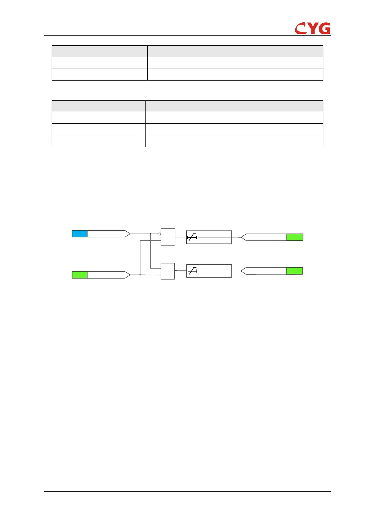
Figure 3-31 Functional module diagram
If there exists binary input signal “MP_BI” and no block signal is activated, the timer and MP_Str
signal are activated.
The time characteristic is according to DT. When the operation timer has reached the value set by
MP_T, the output of mechanical protection is activated. If the fault disappears before the module
operates, the output will reset with a time delay of 30 ms.
The output of mechanical protection depends on setting MP_Op_Ena (The default value is
Disable):
When MP_Op_Ena = Enable, the output MP_Op is activated;
When MP_Op_Ena = Disable, the output MP_Alm is activated;
The binary input MP_Blk can be used to block the function. The activation of the MP_Blk input
deactivates all outputs and resets internal timers.
Where:
MP_Op_Ena is used to control the output of mechanical protection.
Mp_T is the time delay of mechanical protection.