Protection Functions
PRS-7367 231
3.52 Synchronous Motor Loss of Excitation 40O
3.52.1 Overview
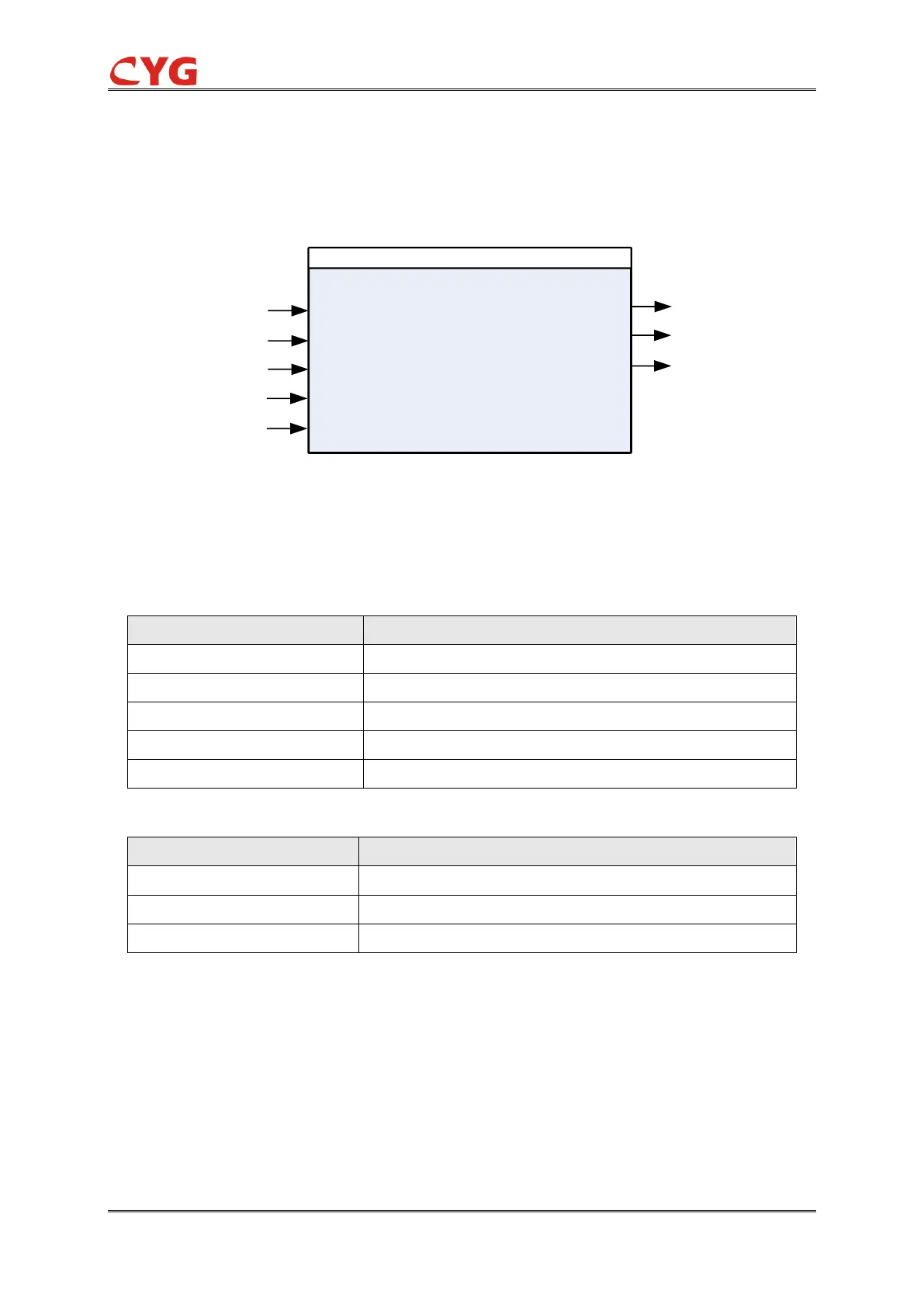
1.1.1.3. Function Block
Out-of-Excitation
U3P
Str
Op
Alm
I3P
Block
PTS
CB Open
Figure 3.52-1 Function block
1.1.1.4. Signals
Table 3.52-1 Input signal
The voltage magnitude in all the three phases
The current magnitude in all the three phases
This signal blocks all the binary output signals of the function
Table 3.52-2 Output signal
3.52.2 Principle
The loss of excitation protection adopts the principle of asynchronous boundary condition
impedance circle. The condition for the loss of excitation protection action is when the positive
sequence impedance of the measuring machine end falls within the asynchronous boundary circle.
The impedance characteristics are shown in the following figure: