Protection Functions
148 PRS-7367
3.28.1.2 Signals
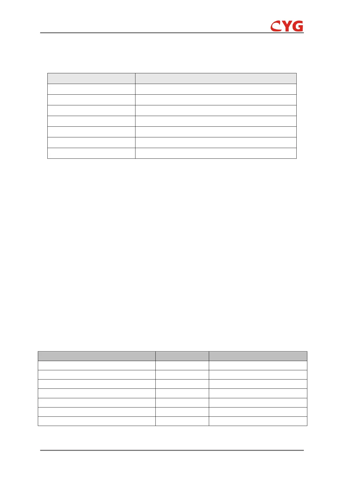
Table 3.28-1 Input Signals
The voltage magnitude in all the three phases
The current magnitude in all the three phases
This signal blocks all the binary output signals of the function
This signal trigger the relay
This signal is to select that the phase A is fault phase
This signal is to select that the phase B is fault phase
This signal is to select that the phase C is fault phase
Note: the TriggA/B/C can be configured to null, if null, the default Fault phases are up to the FPS element.
3.28.2 21FL Protection Principle
The function can be enabled and disabled with the Operation setting. The corresponding
parameter values are "On" and "Off".
The actual fault distance calculation consists of two steps. The fault type is determined first by
using the trigger information. After this, the fault distance is calculated. As a fundamental operation
criterion, the maximum of the phase current magnitudes must exceed a threshold value of 0.1In, In
is the CT secondary current. When this condition is not met, all the outputs of the function are
blocked.
3.28.2.1 Fault type selection
The identification of the faulty phases is compulsory for the correct operation of the fault locator
function. This is because only one of the impedance measuring elements, that is, the fault type,
provides the correct result. A three-phase fault is an exception and it could, in theory, be calculated
with any of the fault loops, in this relay, the phase BC is used. The fault type is determined by the
input of trigger information, as shown in table.
Table 3.28-2 the fault type is determined by trigger information
21FL_SELA=1, 21FL_SELB=0, 21FL_SELC=0
UA/(IA+K*3I0),K=(Z0-Z1)/(3*Z1)
21FL_SELA=0, 21FL_SELB=1, 21FL_SELC=0
UB/(IB+K*3I0) ,K=(Z0-Z1)/(3*Z1)
21FL_SELA=0, 21FL_SELB=0, 21FL_SELC=1
UC/(IC+K*3I0) ,K=(Z0-Z1)/(3*Z1)
21FL_SELA=1, 21FL_SELB=1, 21FL_SELC=0
21FL_SELA=0, 21FL_SELB=1, 21FL_SELC=1
21FL_SELA=1, 21FL_SELB=0, 21FL_SELC=1
21FL_SELA=1, 21FL_SELB=1, 21FL_SELC=1
For phase overcurrent protection, if the TriggA/B/C are invalid, the 21FL protection can be