Protection Functions
206 PRS-7367
failure;
When “CTS_Blk_Ena” is set to “0”, REF protection would not be blocked in case of CT circuit
failure.
Where
:
It should be noted that CT circuit failure induced blocking is principally designed to prevent
malfunction of differential protection caused by CT circuit failure and follows the following
principles:
Firstly, concurrence of multi-side CT circuit failure is not taken into account; secondly, differential
protection trip is allowed in case of concurrence of failure and CT circuit failure; thirdly, relevant
protection should be blocked when fault occurs after CT circuit failure; fourthly, protection shall
operate if CT circuit failure occurs after the occurrence of fault.
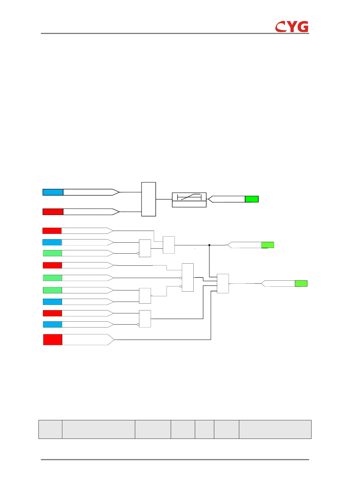
3.42.3 Logic Diagram
Figure 3.42-3 Logic diagram of restricted earth fault protection
Where
:
I0neu is the neutral measured residual current
3.42.4 Settings
Table 3.42-3 Settings of restricted earth fault protection