5.4 Binary Input
5.4.1 Function Description
PRS-7367 relay can collect BI signals, and each BI shall generate reflection records after
undergoing optoelectronic isolation and software impulse filtering.
Parameter setting of status signal quantity contains the following items:
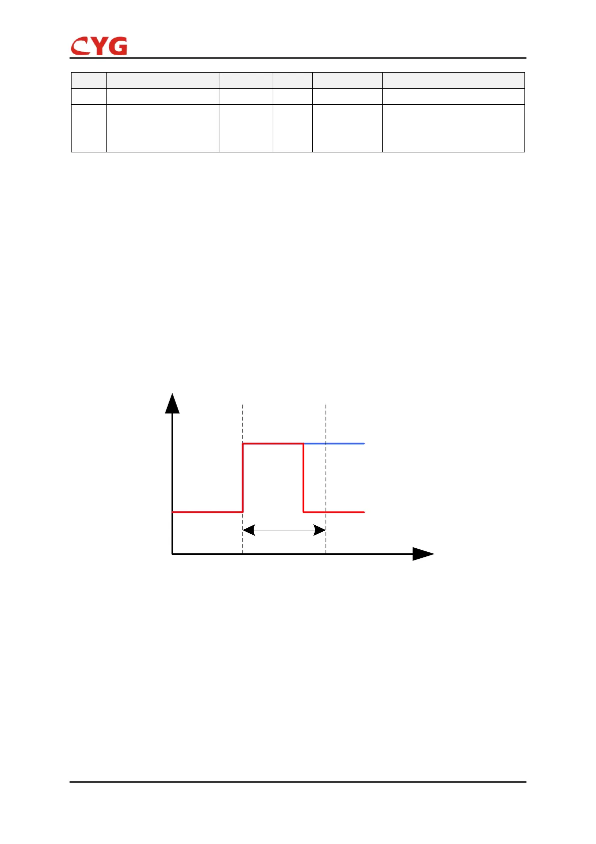
After the filter circuit and debouncing algorithm processing, external interference can be filtered
effectively. As shown in the following figure, a well-designed debouncing technique is adopted in
this device. Binary input state change within "Debouncing time" (t0-t1 can be set 0~30s) will be
ignored, in order to ensure the accuracy of the signal status. Once there is a confirmation of
change status of signal (start from t1), a SOE record will be noted in the device.
Figure 5.4-1 Debouncing technique for binary input
If any input changes more than a defined number of times (N) in a given period (P), then it shall be
automatically suppressed and indication of this presented to the operator, corresponding LED
alarm lights will be lit. when these fault inputs change less than N in new given period (P), then it
shall be recuperative, corresponding LED alarm lights will be going out. Selection of the variable N
and P can be carried out during system configuration.