Protection Functions
54 PRS-7367
The current magnitude in all the three phases
The PTS alarm block directional OC
This signal blocks all the binary output signals of the function
This signal blocks all the start outputs of the function
This signal blocks all the trip signals of the function.
This signal enables the current multiplier.
Table 3.5-2 Output Signals
This is the integrated start signal
This is the integrated operation signal.
This is the integrated Alarm signal
3.5.2 67G Protection Principle
The directional earth-fault protection function can be enabled or disabled by setting the
corresponding 67G_Ena parameter values as "1" or "0".
The operation of directional earth-fault protection can be described by using a module diagram. All
the modules in the diagram are explained in the next sections.
Directional element
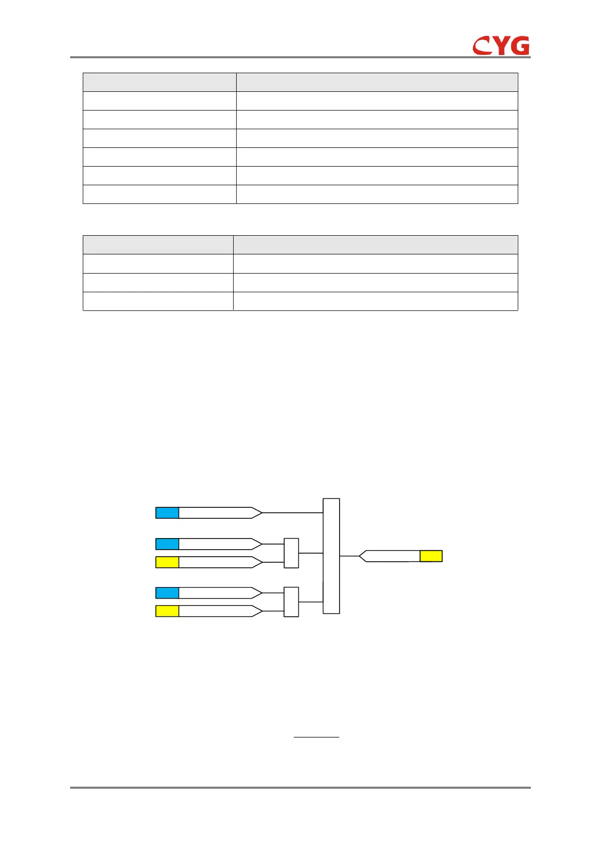
The directional logic diagram of the protection is as below.
1
&
&
67G_Dir_Mod=0SET
67G_Dir_Mod=1SET
FLG Forward Direction
67G_Dir_Mod=2SET
FLG Reverse Direction
Direction Initiation
FLG
Figure 3.5-2 The directional logic diagram
Self-polarizing is used (I
0
-(-U
0
)) to determine the fault direction.
The evaluation of the forward directionality is according to the equation:
)5(90arg)5(90
o
U
jRCA
e
o
I

 Loading...