3.11.2 59 Protection Principle
The three-phase overvoltage protection function can be enabled or disabled by setting the
corresponding 59_Ena parameter values as "1" or "0".
The operation of the three-phase overvoltage protection can be described using a module diagram.
All the modules in the diagram are explained in the next sections.
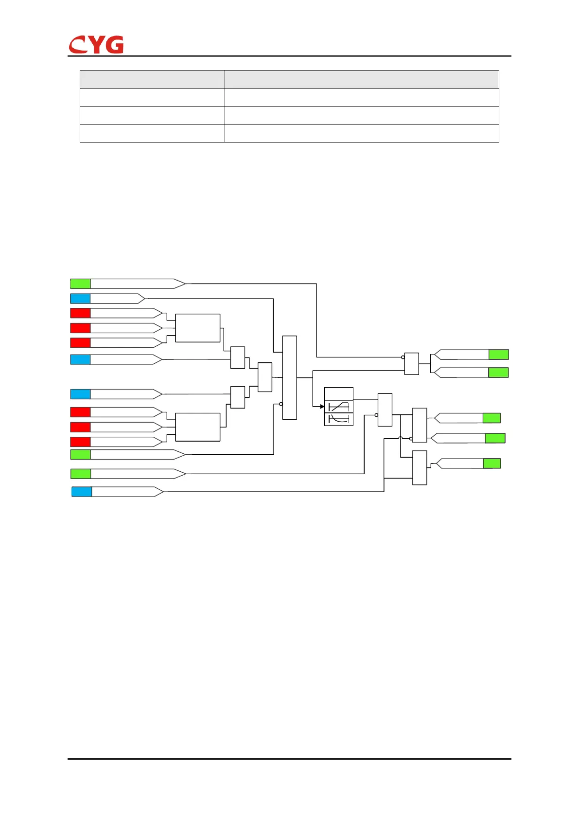
The functional module diagram is shown as below:
Figure 3.11-2 Functional module diagram
The fundamental frequency component of the measured three phase voltages is compared
phase-wise to the set value of the 59_Vol_Str setting. If the measured value is higher than the set
value of the 59_Vol_Str setting, the phase selection logic detects the phase or phases in which the
fault level is detected. If the number of faulty phases is equal to or more than the set
59_Str_Ph_Num and no blocking signal input is activated, the phase selection logic activates the
timer and the 59_Str output and the corresponding output of the respective phases
(59_Str_A/B/C).
Where:
The 59_Vol_Select setting is used for selecting phase-to-earth (59_Vol_Select=1) or
phase-to-phase(59_Vol_Select=2) voltages for protection.
59_Vol_Str is the preset value to check for the voltage