Protection Functions
PRS-7367 109
3.20.1.1 Function Block
The function block of the protection is as below.
U3P
UFRE_81U
Blk
Str
Op
81U_Act
Figure 3.20-1 Function block
3.20.1.2 Signals
Table 3.20-1 Input Signals
The voltage magnitude in all the three phases
This signal blocks all the binary output signals of the function
This 81U operation signal.
Table 3.20-2 Output Signals
This is the integrated start signal.
This is the integrated operation signal.
3.20.2 81URE Protection Principle
The under frequency restore protection function can be enabled or disabled by setting the
corresponding 81URE_Ena parameter values as "1" or "0".
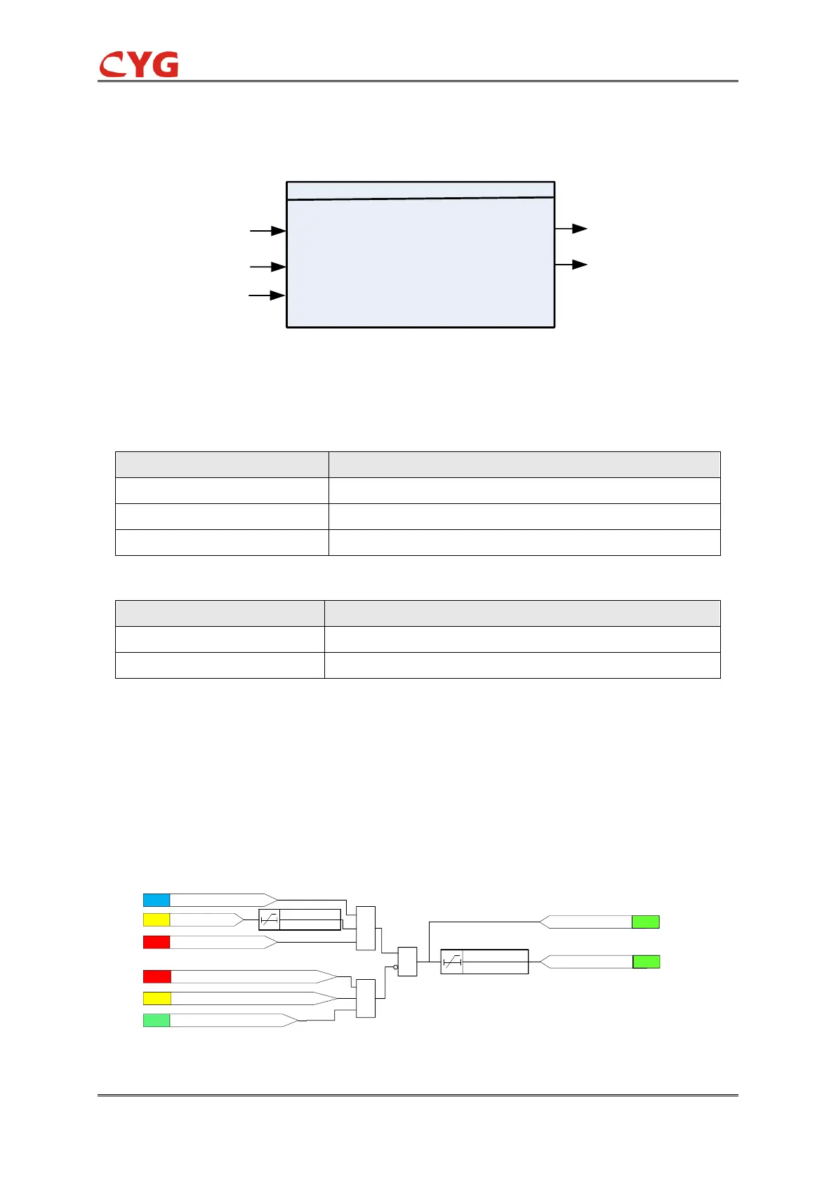
The operation of under frequency restore protection can be described by using a module diagram.
All the modules in the diagram are explained in the next sections.
The functional module diagram is shown as below:
≥
1
&
&
SIG
81URE_Str
81URE_Ena=1
ANA
MinUpp<81URE_Vol_Blk
SET
30ms
FLG
f>(fn+20)Hz or f<(fn-20)Hz
ANA
Fr>81URE_Fr_Str
SIG
81URE_Blk=1
81URE_Op_T
81URS_Op
FLG
81URE_Valid_T
0
SIG
81URE_Op
Figure 3.20-2 Functional module diagram