Protection Functions
88 PRS-7367
U3P
59P
Blk
Blk_Op
Blk_Str
Str
Op
Figure 3.12-1 Function block
3.12.1.2 Signals
Table 3.12-1 Input Signals
The voltage in all the three phases
This signal blocks all the binary output signals of the function
This signal blocks all the start outputs of the function
This signal blocks all the trip signals of the function.
Table 3.12-2 Output Signals
This is the integrated start signal
This is the integrated operation signal.
3.12.2 59P Protection Principle
The positive-sequence overvoltage protection function can be enabled or disabled by setting the
corresponding 59P_Ena value as "1" or "0".
The operation of the positive-sequence overvoltage protection can be described using a module
diagram. All the modules in the diagram are explained in the next sections.
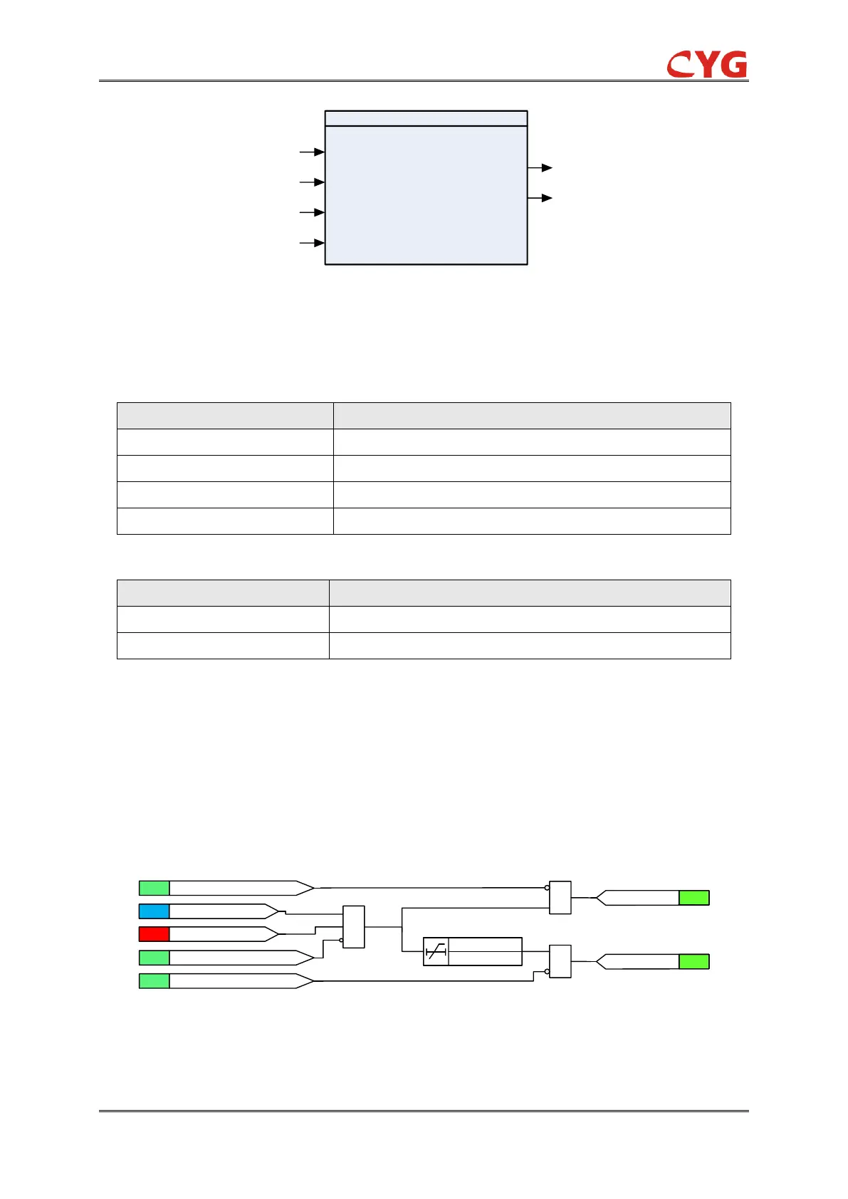
The functional module diagram is shown as below:
&
U1>59P_Vol_Str
ANA
SIG
59P_Op
SIG
59P_Str
SIG
59P_Blk
&
&
SIG
59P_Blk_Str=1
59P_Ena=1
SET
SIG
59P_Blk_Op=1
30ms
59P_Op_T
Figure 3.12-2 Functional module diagram
The calculated positive-sequence voltage is compared to the set 59P_Vol_Str setting. If the value
exceeds the set 59P_Vol_Str and no block signal is activated, the timer and 59P_Str signal are