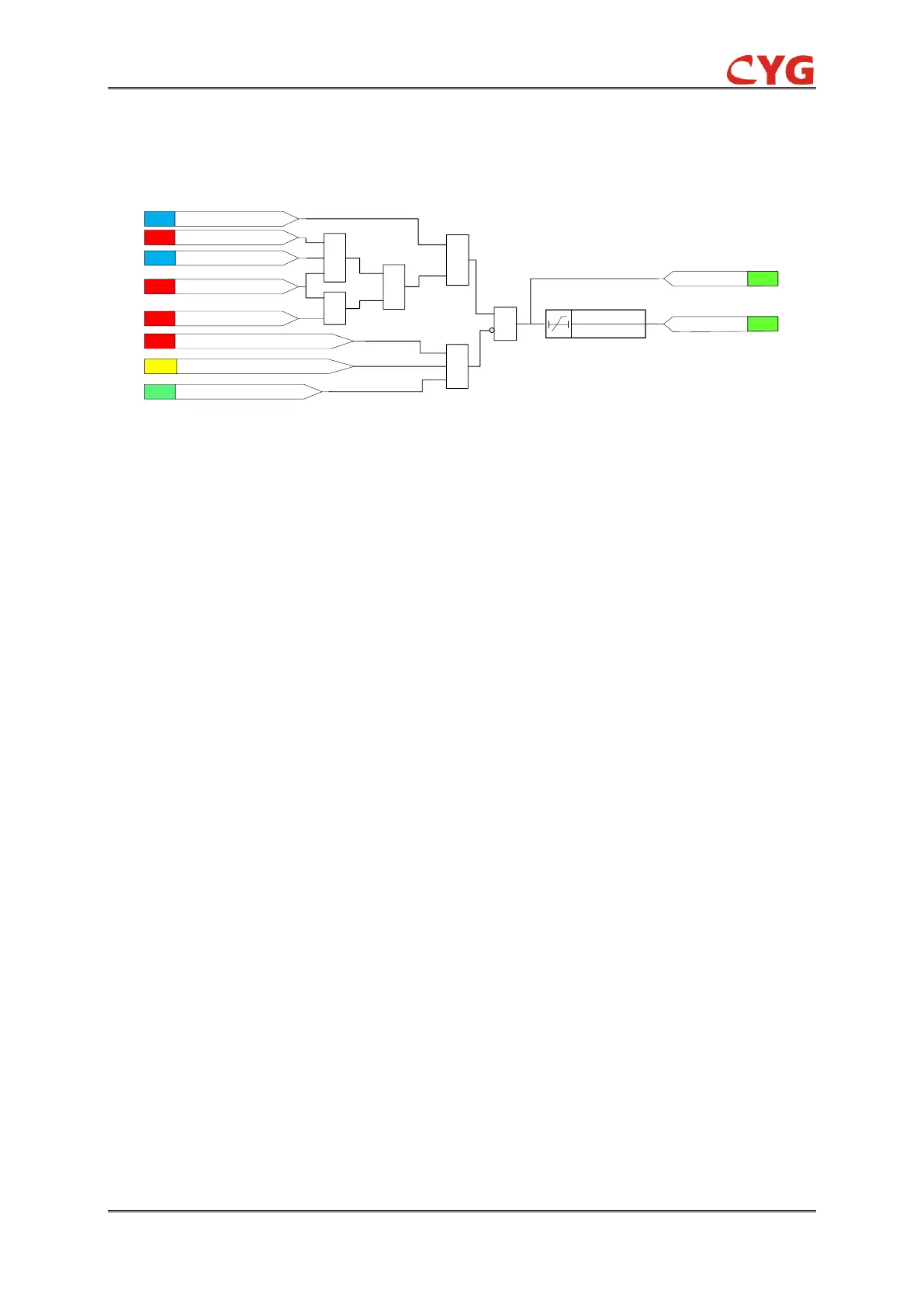
Figure 3.21-2 Functional module diagram
The changing rate of the frequency of the positive sequence voltage is calculated from
phase-to-phase or phase-to-earth voltages and compared to the set 81R_Dfdt_Str. If the
measured frequency changing rate is higher than the set 81R_Dfdt_Str and no block signal is
activated, the operate timer and 81R_Str signal are activated. However, if the voltage magnitude is
below the 81R_Vol_Blk set value or the difference between the measured frequency and the rated
frequency exceeds 20 Hz, the operate timer and 81R_Str signal are deactivated.
81R_Dfdt_Str is the frequency gradient start value. When the setting 81R_FrUp_Ena equals 1, it
means a positive change in frequency. Otherwise, it means a negative change in frequency.
Once activated, the 81R_Str output activates. The time characteristic is according to DT. When the
operation timer has reached the value set by 81R_Op_T, the 81R_Op output is activated. If the
frequency gradient condition disappears before the module operates, the operation resets with a
set time delay of 81R_Reset_T.
The activation of the 81R_Blk input resets the timer and deactivates the 81R_Op and 81R_Str
outputs.
Where:
81R_Op_T is the operation delay time setting of the 81R.
81R_Reset_T is the reset delay time setting of the 81R.
3.21.3 81R Application Scope
81R is applicable in all the situations where the change of the fundamental power system voltage
frequency should be detected reliably. 81R can be used for both increasing and decreasing of the
frequencies.
This function provides a trip signal suitable for load shedding, generator shedding, generator
boosting and gas turbine startup. The frequency gradient is often used in combination with a low
frequency signal, especially in smaller power systems where the loss of a fairly large generator
requires quick remedial actions to secure the power system's integrity.


 To Next Page