EasyManua.ls Logo

CYG PRS-7367 - Logic Diagram; Protection Principle

CYG PRS-7367
360 pages
Print Icon
To Next Page IconTo Next Page
To Previous Page IconTo Previous Page
Loading...
Protection Functions
PRS-7367 209
3.43.2 Logic Diagram
SIG
InstOp=1
3Io>0.08In
ANA
Imin<0.05In
ANA
&
SIG
Op=1
SIG
BLOCK
3U0<10V
ANA
3IoAll>0.08In
ANA
&
60ms
&
Imin<0.05In
ANA
3U0<12V
ANA
3IoAll>0.06In
ANA
&
1
SIG
CT_InsALM=1
20ms
SIG
InstOp=0
SIG
Op=0
1s
10s
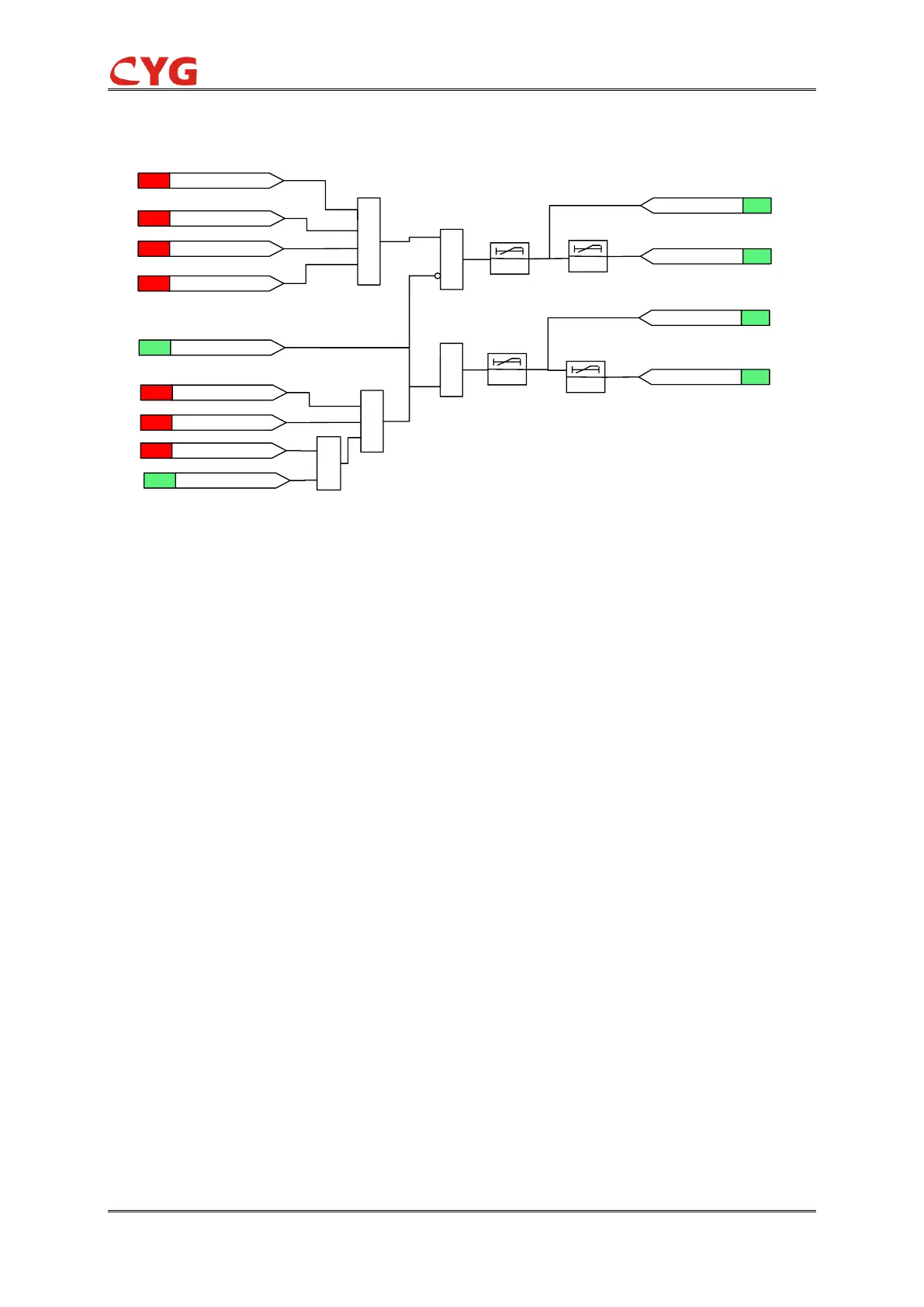
Figure 3.43-1 CTS criterion logic diagram
3.43.3 Protection Principle
This is a backup function of CT circuit failure criterion.
Each side of the device is furnished with CT circuit failure alarm element
To prevent incorrect tripping of zero-sequence overcurrent protection caused by CT circuit failure
or anomaly, the device is provided with CT circuit failure judgment element using the following
criterion:
CT
CT
UU
II
00
00
3
3
Where
TA
I
0
=0.08In: zero-sequence current
TA
U
0
=10V: zero-sequence voltage
CT circuit failure will be deemed to have occurred once the situation that meets above-noted
criterion lasting for 10s.

Table of Contents