Protection Functions
PRS-7367 49
This signal enables the current multiplier.
Table 3.4-2 Output Signals
This is the integrated start signal
This is the integrated operation signal.
This is the integrated Alarm signal
3.4.2 51G Protection Principle
3.4.2.1 51G
The earth-fault protection function can be enabled or disabled by setting the corresponding
51G_Ena parameter values as "1" or "0".
The residual current sample method is determined by 51G_3I0_Calc_Ena, if
51G1_3I0_Calc_Ena=0, the current is sample from external terminal, if 51G1_3I0_Calc_Ena=1,
the current is calculated by three phases current.
The operation of non-directional earth-fault protection can be described by using a module
diagram. All the modules in the diagram are explained in the next sections.
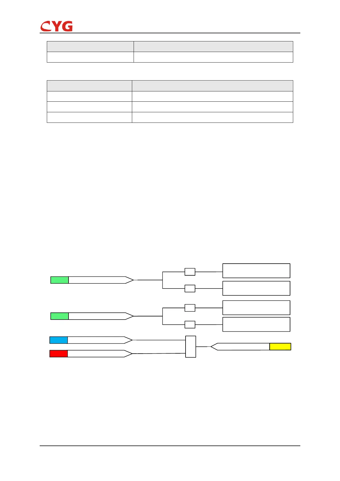
Initiation element
The initiation logic diagram is shown as below:
&
51G_Ena=1
SET
Io>Set Value
ANA
Initiation
FLG
=0
=1
Io=3Io
SIG
51G_3Io_Calc_Ena
Io=3IoD
=0
=1
Set Value = 51G_Cur_Str
Set Value =51G_Cur_Str
*51G_Mult_I
SIG
51G_Ena_Mult
Figure 3.4-2 Initiation logic diagram for 51G
If the 51G_3Io_Calc_Ena input is active, the internally calculated residual current is configured to
be available for the protection function it will be used as operating quantity. Otherwise the
measured residual current is used. The operating quantity is compared to the set 51G_Cur_Str. If
the measured value exceeds the set 51G_Cur_Str, the level detector sends an Initiation signal to
the timer module.