Protection Functions
50 PRS-7367
The 51G_Cur_Str setting is multiplied by the 51G_Mult_Cur setting.
Where
:
51G_Cur_Str is the start value of 51G.
51G_Mult_Cur is the multiplier for scaling the start value.
NOTICE!
Do not set the multiplier setting 51G_Mult_Cur higher than necessary. If the value is too
high, the function may not operate at all during an inrush followed by a fault, no matter
how severe the fault is.
The start value multiplication is normally done when the inrush detection function
(OCR_INR) is connected to the Ena_Mult input by Three phase inrush function
OCR_INR.
Timer element
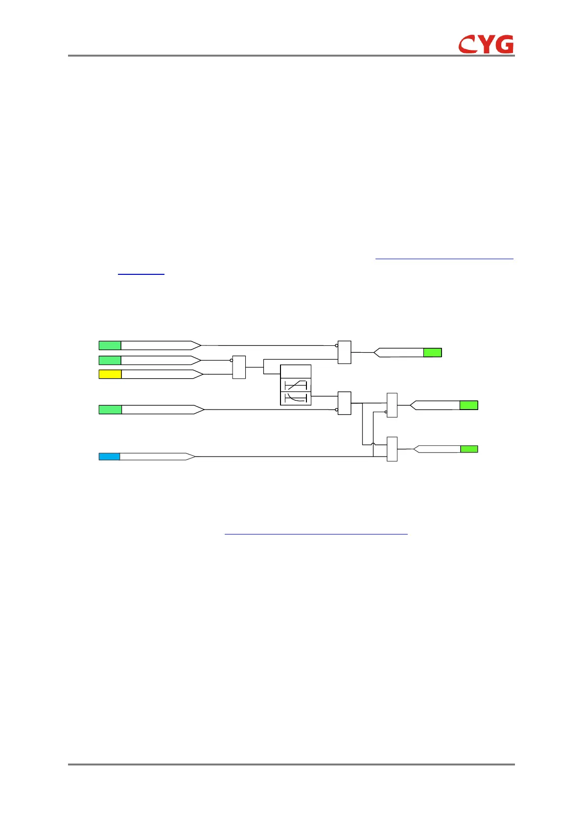
The functional module diagram is shown as below:
Figure 3.4-3 Functional module diagram for 51G.
Once initiation logic is fulfilled and no 51G_Blk signal is activated, the 51G_Str signal is activated.
The timer model is determined by IDMT curves for over quantity protection.
The operation is activated after the operation timer has reached the calculated value. However,
51G_Min_Op_T defines the minimum desired operate time for IDMT. If a drop-off situation
happens, that is, a fault suddenly disappears before the operate delay is exceeded, the operation
will reset after the set value 51G_Reset_T is exceeded.
NOTICE!
The 51G_Min_Op_T setting should be used with great care because the operation time
is according to the IDMT curve, but always at least the value of the 51G_Min_Op_T
setting.
The binary input 51G_Blk can be used to block the function. The activation of the 51G_Blk input
deactivates all outputs and resets internal timers. The binary input 51G_Blk_Str can be used to
block the 51G_Str signals. The binary input 51G_Blk_Op can be used to block the 51G_Op
signals.