Protection Functions
138 PRS-7367
This signal blocks all the start outputs of the function
This signal blocks all the trip signals of the function.
This signal enables the current multiplier.
Table 3.25-2 Output signal
This is the integrated start signal
This is the start signal of phase A
This is the start signal of phase B
This is the start signal of phase C.
This is the integrated operation signal.
This is the operation signal of phase A
This is the operation signal of phase B
This is the operation signal of phase C
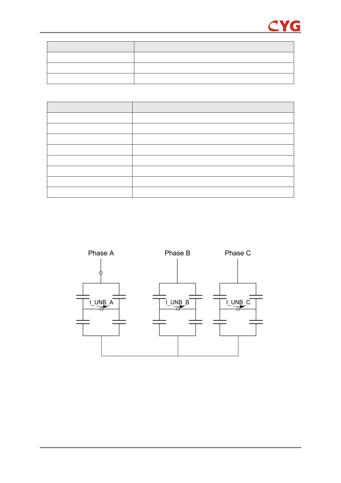
3.25.2 51NT Protection Principle
In the three-phase H-bridge-connected shunt capacitor bank configuration, the unbalance currents
I_UNB_A, I_UNB_B and I_UNB_C are measured at the common points of the H-bridge.
Figure 3.25-2 H-Bridge-connected capacitor bank
The protection function can be enabled or disabled by setting the corresponding 51NT_Ena as "1"
or "0".
The operation of the three phase unbalance protection can be described using a module diagram.
All the modules in the diagram are explained in the next sections.