Protection Functions
PRS-7367 139
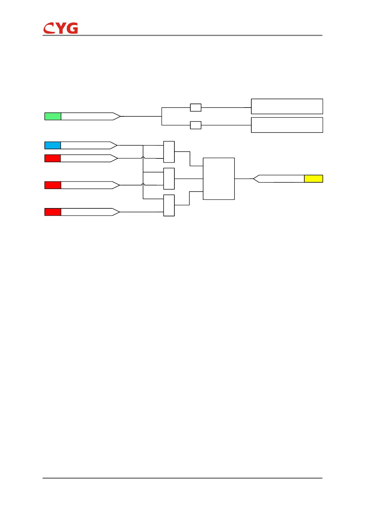
3.25.2.1 Initiation logic
The initiation of three-phase current unbalance protection can be described by using a module
diagram. The functional module diagram is shown as below: the unbalance currents I_UNB_A,
I_UNB_B, I_UNB_C are sampled in device by Ia2, Ib2, Ic2.
Figure 3.25-3 Initiation module diagram
The measured three phase unbalance currents are compared to the set 51NT_Cur_Str. If the
measured value exceeds the set 51NT_Cur_Str, the level detector reports the exceeding of the
value to the phase selection logic. If the 51NT_Ena_Mult input is active, the 51NT_Cur_Str value
setting is multiplied by the 51NT_Mult_Cur setting.
If the fault criteria are fulfilled in the level detector, the phase selection logic detects the phase or
phases in which the measured current exceeds the setting. If the phase information is equal to or
more than the 51NT_Str_Ph_Num setting, the phase selection logic activates the “Initiation”
signal.
Where :
51NT_Ena_Mult is a binary input to enable or disable the start multiplier.
51NT_Ena is used to enable or disable the protection.
51NT_Cur_Str is the 51NT start value.
51NT_Mult_Cur is the multiplier for scaling the start value.
51NT_Str_Ph_Num is the Number of phases required for activation.
NOTICE!
Do not set the multiplier setting 51NT_Mult_Cur higher than necessary. If the value is
too high, the function may not operate at all during an inrush followed by a fault, no
matter how severe the fault is.