Monitoring & Control
250 PRS-7367
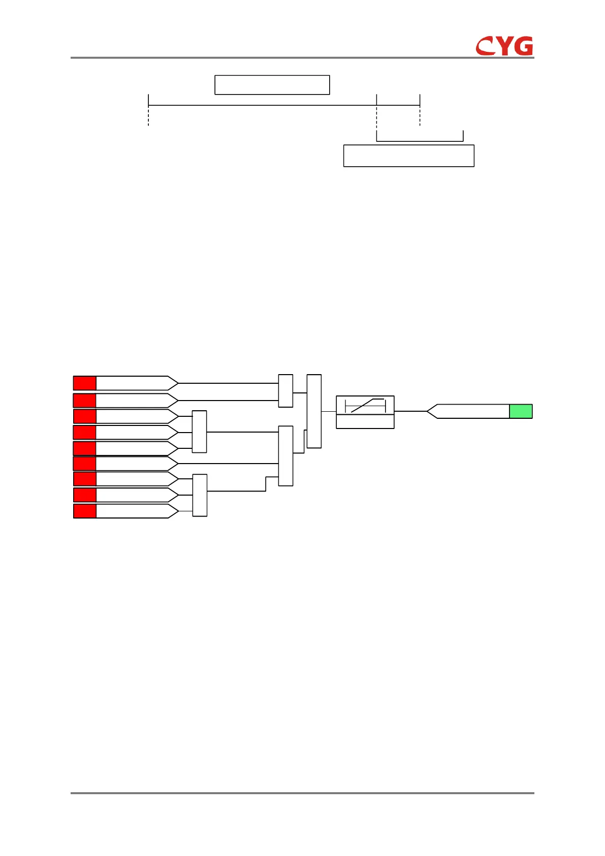
SetSN_Sync_RESETIME
Treset
0
T1
SetSN_Sync_NoVolTDalay or
SetSN_Sync_LoopTDelay
0
Synchrocheck not OK
Synchrocheck OK
Figure 5.2.3-3 Logic diagram of the special case
5.2.4 25SYN Check Block
PT disconnection monitoring is to lock the synchronization function when the connection between
the PT secondary circuit and the device fails, to prevent possible malfunction.
There are two main logics in this function:
1) System zero sequence voltage(U0) or negative sequence voltage (U2) is greater than 10%Un;
2) No voltage on the system side but current: Any system phase voltage(Ua、Ub、Uc) is less than
30%Un, system positive sequence voltage(U1) is less than 70%Un, and any system
current(Ia,Ib,Ic) is greater than 0.5%In;
25SYN_T_SynChk / 0
SIG25SYN_SYNC_BLOCK
U0 > 10%UnANA
Ua < 30%UnANA
U1 < 70%UnANA
Ia > 0.5%InANA
Ib > 0.5%InANA
Ic > 0.5%InANA
&
1
1
1
U2 > 10%UnANA
Ub < 30%UnANA
Uc < 30%UnANA
1
Figure 5.2.4-1 Logic diagram of the 25SYN Check Block function
NOTICE!
During the Synchro check, if SYNC_BLOCK is established, the 25SYN function is blocked
and the module considers the analog that device acquired is invalid. So 25SYN will no longer
judge other synchronization logic and all logic results will be cleaned.
5.2.5 25SYN Application Scope
Energy Check
Energizing check the subsystem of synchro check is to make easier the regulated or monitored
disconnected transmission lines or buses to connect again with energized transmission lines or
buses as soon as possible. The main and important application of the energizing check module is
to reconnect dead network of power system (T/L or buses) with energized or working network of
power system.