EasyManuals Logo

CYG PRS-7367 User Manual

CYG PRS-7367
360 pages
To Next Page IconTo Next Page
To Previous Page IconTo Previous Page
Page #142 background imageLoading...
Page #142 background image
Protection Functions
134 PRS-7367
3.24.1.2 Signals
Table 3.24-1 Input Signals
Signal
Description
I3P
The current magnitude in all the three phases
51NA_Blk
This signal blocks all the binary output signals of the function
51NA_Blk _Str
This signal blocks all the start outputs of the function
51NA_Blk _Op
This signal blocks all the trip signals of the function.
51NA_Ena_Mult
This signal enables the current multiplier.
Table 3.24-2 Output Signals
Signal
Description
51NA_Str
This is the integrated start signal.
51NA_Op
This is the integrated operation signal.
3.24.2 51NA Protection Principle
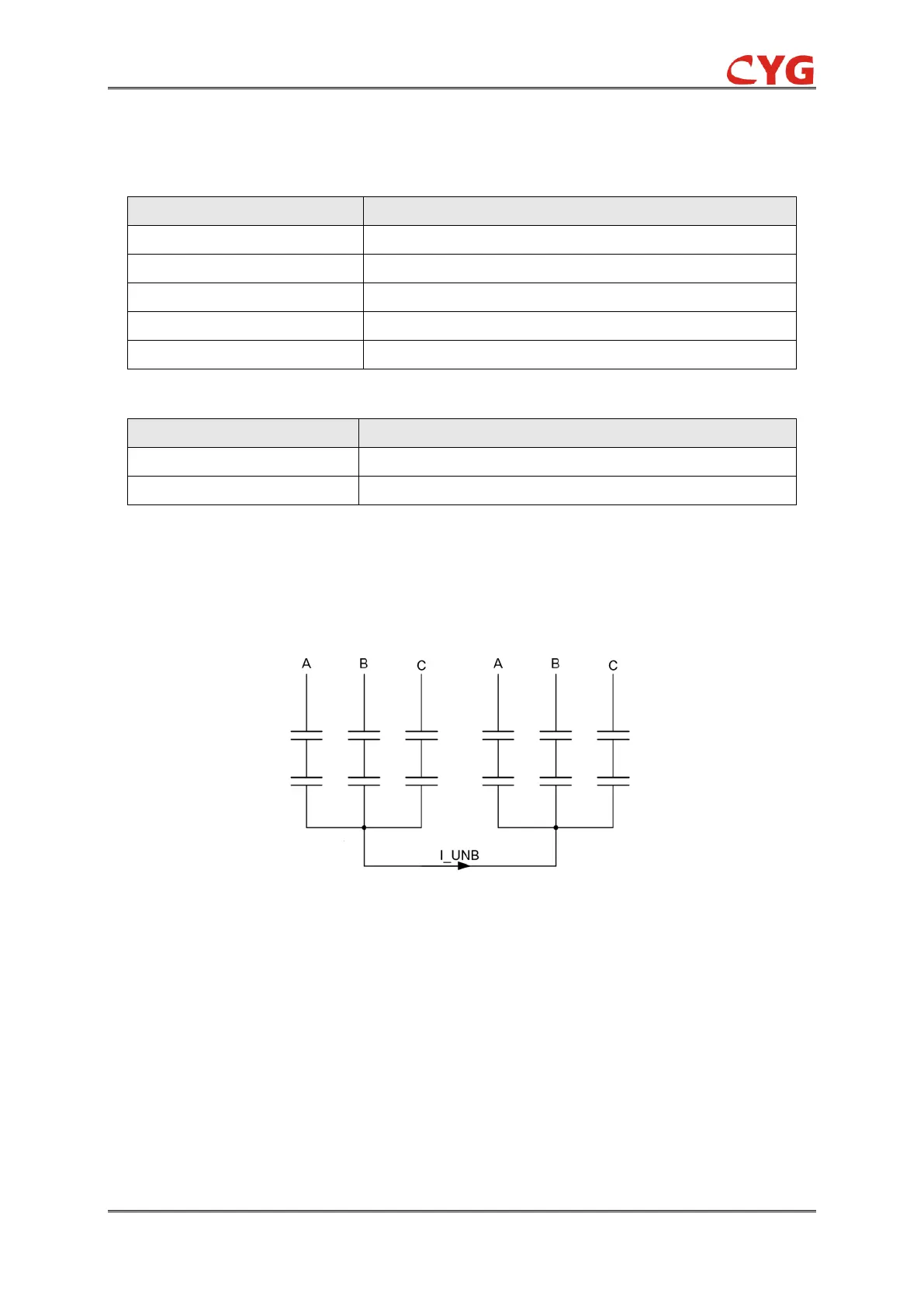
A standard Double-Y-connected shunt capacitor bank configuration is shown in following diagram.
The fundamental frequency component of an unbalance current is measured on the common
neutral connecting the two balanced parts of a shunt capacitor bank.
Figure 3.24-2 The neutral balance current of Double-Y-connected capacitor bank
The function can be enabled and disabled with the Operation setting. The corresponding
parameter values are “On” and “Off”. The operation of 51NA can be described by using a module
diagram. All the modules in the diagram are explained in the next sections.
3.24.2.1 Initiation logic
The initiation of neutral current unbalance protection can be described by using a module diagram.
The functional module diagram is shown as below: the unbalance current I_UNB is sampled in
device by Ia2 current.

Table of Contents

Questions and Answers:

Question and Answer IconNeed help?

Do you have a question about the CYG PRS-7367 and is the answer not in the manual?

CYG PRS-7367 Specifications

General IconGeneral
BrandCYG
ModelPRS-7367
CategoryControl Unit
LanguageEnglish