Protection Functions
PRS-7367 143
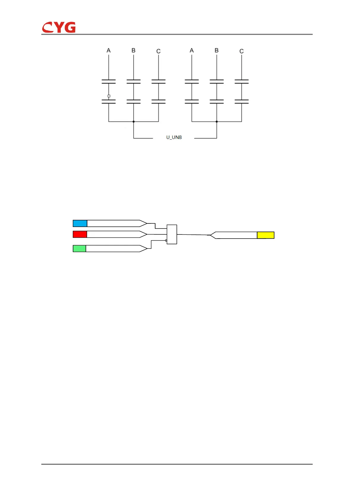
Figure 3.26-2 The neutral balance voltage of Double-Y-connected capacitor bank
3.26.2.1 Initiation logic
The initiation of neutral voltage unbalance protection can be described by using a module diagram.
The functional module diagram is shown as below: the unbalance voltage U_UNB is sampled in
device by Ua2.
Figure 3.26-3 The initiation diagram
The measured neutral unbalance voltage is compared to the set 59NA_Vol_Str. If the measured
value exceeds the set 59NA_Vol_Str and no block signal is activated, the timer and 59NA_Str
signal are activated.
Where:
59NA_Ena is used to enable or disable the protection.
59NA_Vol_Str is the start value.
3.26.2.2 Timer element
The functional module diagram is shown as below: