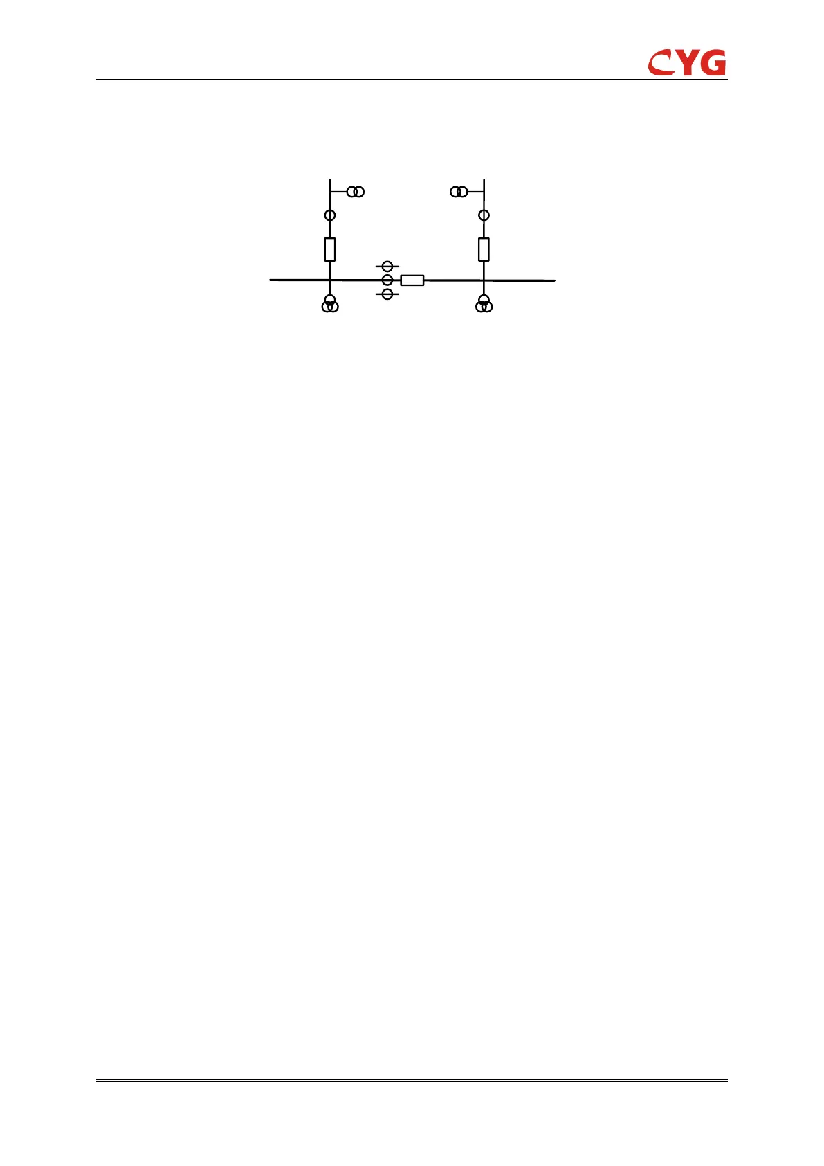
Figure 3.34-1 Main wiring diagram of backup power automatic switch
The charge conditions of backup power automatic switching including:
1) No blocking condition, discharge condition;
2) Backup power automatic switching device is enabled;
3) Operating and backup breakers are in normal position;
4) Operating and backup power supply are in good condition.
Backup power automatic switching does not operate unless the device is charged for 15s
after all charge conditions are satisfied.
After backup power automatic switching is completed charged, in case of busbar voltage
failure, no current at operating incoming line and backup power supply live voltage, backup power
automatic switching device activates the delay; when the delay time is elapsed, the device will trip
operating incoming line while determining whether it has been tripped off.
Backup power automatic switching of incoming line has two operation modes, Backup power
automatic switching of incoming line 1 (BPAS1) and backup power automatic switching of
incoming line 2 (BPAS2). In these two operation modes, incoming line 1 and 2 alternate each
other in an obvious manner, that means, CB01 and CB02 are alternate for each other.
The operation process of BPAS1 is tripping CB01 and closing CB02 when busbar 1 and 2 are
in dead voltage status;
The operation process of BPAS2 is tripping CB02 and closing CB01 when busbar 1 and 2 are
in dead voltage status.
Backup power automatic switching of busbar has two operation modes, Backup power
automatic switching of busbar 1 (BPAS3) and backup power automatic switching of busbar 2