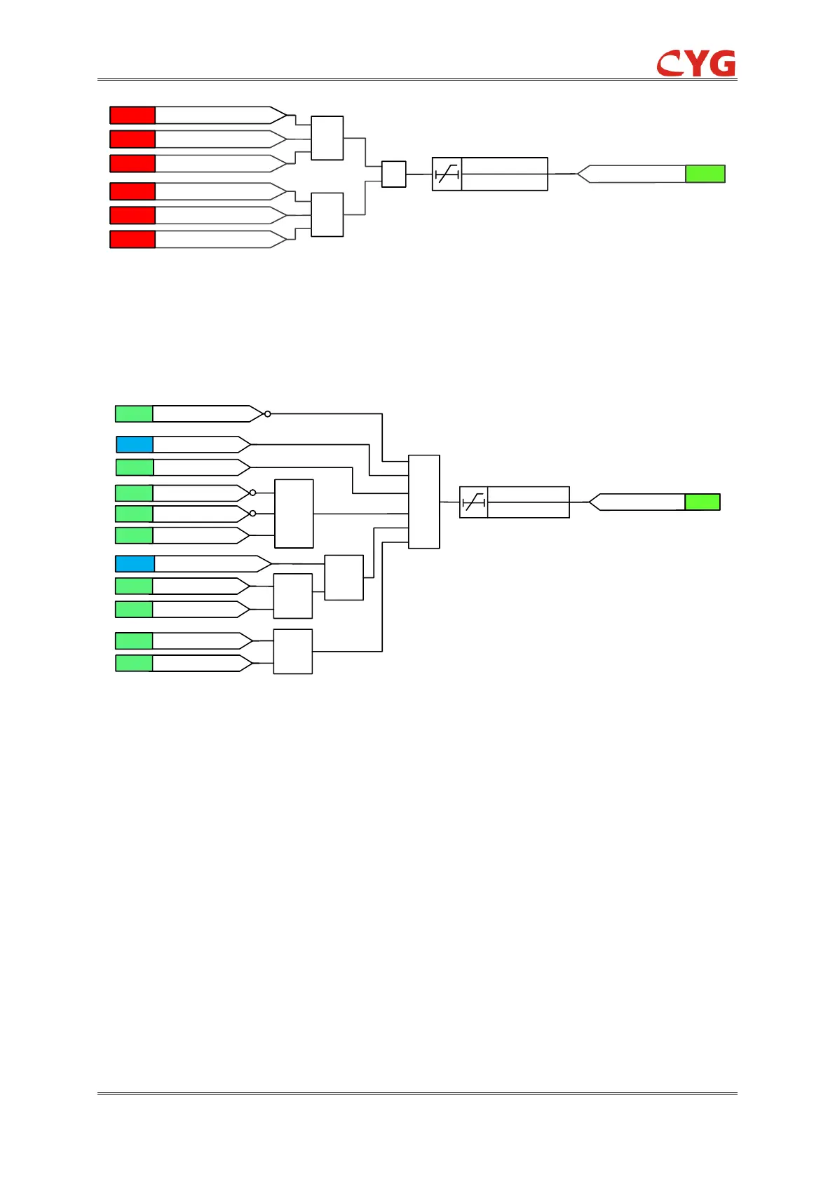
Figure 3.34-14 Diagram of busbar voltage loss logic
7) Operating breaker fails to trip or backup breaker fails to close.
Charge Conditions
The logic diagrams of the charge condition of BPAS3 is shown in Figure 3.34-15.
Figure 3.34-15 Diagram of the charge condition of BPAS3
The charge conditions of BPAS3 and BPAS4 are similar, so take BPAS3 for example.
The charge conditions of BPAS3 cover the following items:
1) No blocking condition, discharge condition;
2) Backup power automatic switching device is enabled, that means, the setting value
BPAS3_Ena is “enabled”;
3) Operating and backup breakers are in normal position, that means, CB01 and CB02 are
at close position, while CB03 is at open position;
4) CB01 and CB02 are in after-close status. If there's no CB after-close binary inputs, the
criterion could be disabled through setting CB_Aft_Cls_Ena.
5) Both busbar 1 and busbar 2 are in good condition, i.e. meeting live voltage condition;
Backup power automatic switching does not operate unless the device is charged for 15s