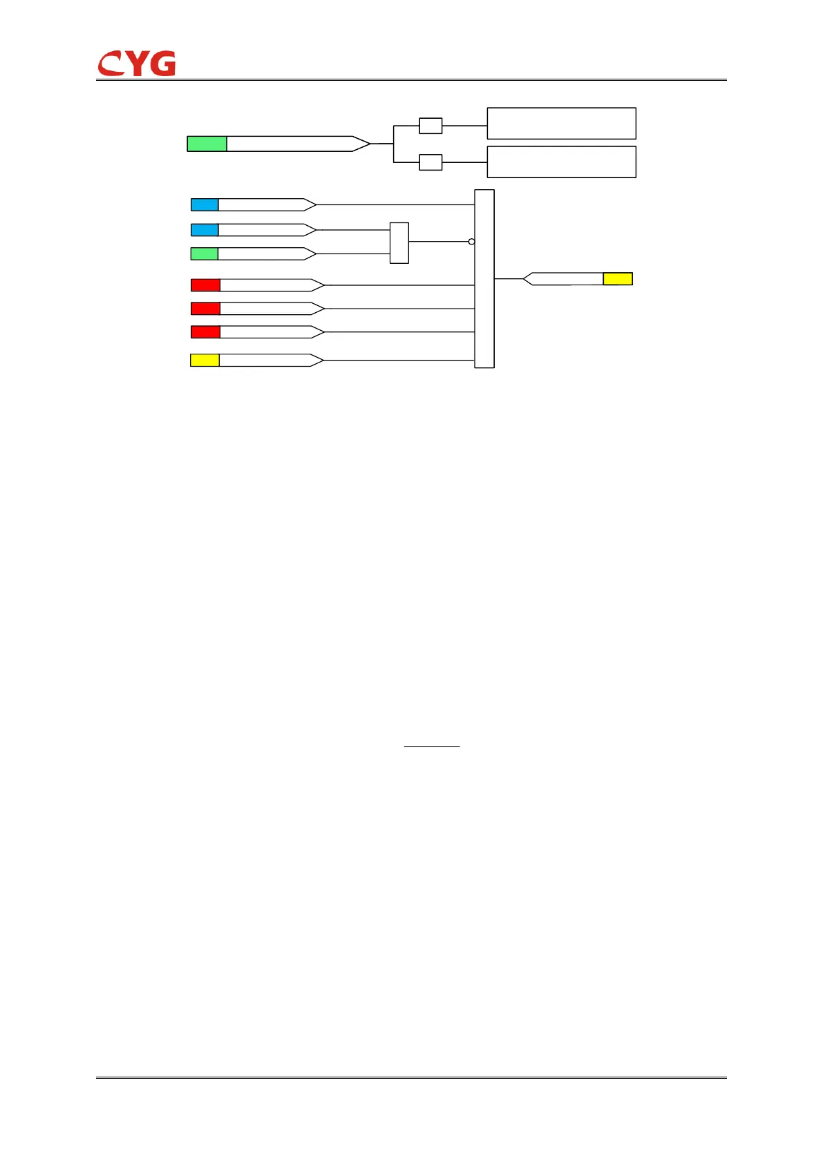
Figure 3.38-2 Wattmetric SEF Initiation Logic
The level detector compares the magnitudes of the measured operating quantity, polarizing
quantity and calculated residual power to the set Current start value, Voltage start value and Res
power start value respectively. When all three quantities exceed the limits, the relay initialized.
Timer
Once initiation logic is fulfilled and no blocking signal is activated, the Start signal is set. The timer
model is determined by depending on the value of the Operating curve type setting, the time
characteristics are according to DT or Wattmetric IDMT. When the operation timer has reached the
value of operate delay time in the DT mode or the maximum value defined by the inverse time
curve, the Operate output is activated. If a drop-off situation happens, that is, a fault suddenly
disappears before the operate delay is exceeded, the timer reset state is activated. The reset time
is DT and depends on the Reset delay time setting.
Wattmetric IDMT:
Where:
T = Operation time in seconds
k = Setting value of Timer multiplier
Pref= Setting value of Reference power
Pcal=Caculated residule power
The operation type can be set to trip or alarm by setting.