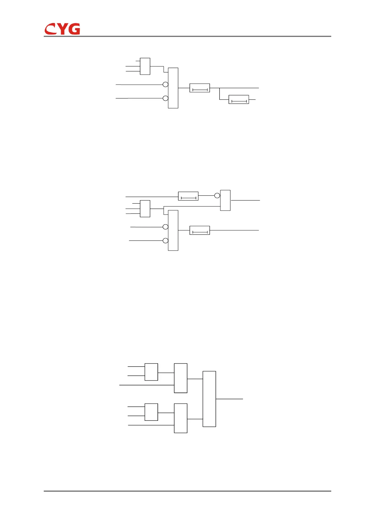
Figure 3.40-3 Transformer Block Busbar Protection
3) When used as section protection, connect the output of Block Busbar trip to the terminal of
"Block BusOp", and output Block Busbar block and trip. Block1,2 are the overcurrent block of I and
II bus feeder respectively. The bus block is realized through "current block" logic, which is as
follows:
Figure 3.40-4 Section Block Busbar Protection
4) Current Block: Usually used in combination with the block logic of sectional Block Busbar
protection, as feeder overcurrent block logic, it can be used for Busbar I or Busbar II. Taking
Busbar I as an example, the default number of feeder i is 16 at most, that is, there are 16
overcurrent block inputs such as IL1~16, and each block input can be respectively cast back
through the softswitch. If any feeder ILI (I =1~16) is enabled and the BIs of ILI (I =1~16)
overcurrent block is 1 and there is no chain break blocking, then the overcurrent blocking condition
of Busbar I feeder is satisfied. The logic is as follows: