EasyManuals Logo

CYG PRS-7367 User Manual

CYG PRS-7367
360 pages
To Next Page IconTo Next Page
To Previous Page IconTo Previous Page
Page #276 background imageLoading...
Page #276 background image
Hardware
268 PRS-7367
Figure 6.1-2 Front panel of this relay
·
·
01
02
03
04
05
06
07
08
09
10
11
12
13
14
15
16
I/O
·
I/O
Analog
Power
I/O
·
·
01
02
03
04
05
06
07
08
09
10
11
12
13
14
15
16
·
01
02
03
04
05
06
07
08
09
10
11
12
13
14
15
16
01
02
03
04
05
06
07
08
09
10
11
12
13
14
15
16
01
02
03
04
05
06
07
08
09
10
11
12
13
14
15
16
01
02
03
04
05
06
07
08
09
10
11
12
13
14
15
16
CPU
IRIG-B
RX
01
03
05
07
09
02
04
06
08
10
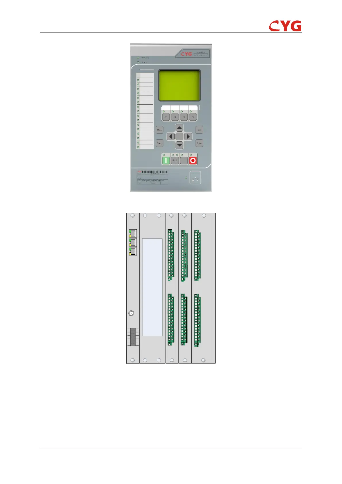
Figure 6.1-3 Rear panel of this relay
NOTICE!
The hardware module configuration in the above figure is only for demonstrating one
kind of typical configuration. Most often, the configuration has to be modified in most of
the project. The hardware module configuration of a practical engineering should be
modified based on the practical designing requirement.

Table of Contents

Questions and Answers:

Question and Answer IconNeed help?

Do you have a question about the CYG PRS-7367 and is the answer not in the manual?

CYG PRS-7367 Specifications

General IconGeneral
BrandCYG
ModelPRS-7367
CategoryControl Unit
LanguageEnglish