EasyManua.ls Logo

CYG PRS-7367 - Page 278

CYG PRS-7367
360 pages
Print Icon
To Next Page IconTo Next Page
To Previous Page IconTo Previous Page
Loading...
Hardware
270 PRS-7367
19
20
21
22
23
24
25
26
27
28
29
30
31
32
POW(+)
POW(-)
Dev_Err
Common
Dev_Err
Cls
Dev_Err
Open
BO02
Open
BO03
Common
BO01
Open
BO02
Common
01
02
03
04
05
06
07
08
09
10
11
12
13
14
15
16
PWR
BO03
Open
BO04
Common
BO04
Open
BO05
Common
BO01
Common
BO05
Open
BO06
Common
BO06
Open
BO07
Common
BO07
Open
BO07
Cls
BO08
Common
BO08
Open
BO08
Cls
BO09
Common
BO09
Cls
BO09
Open
18
17
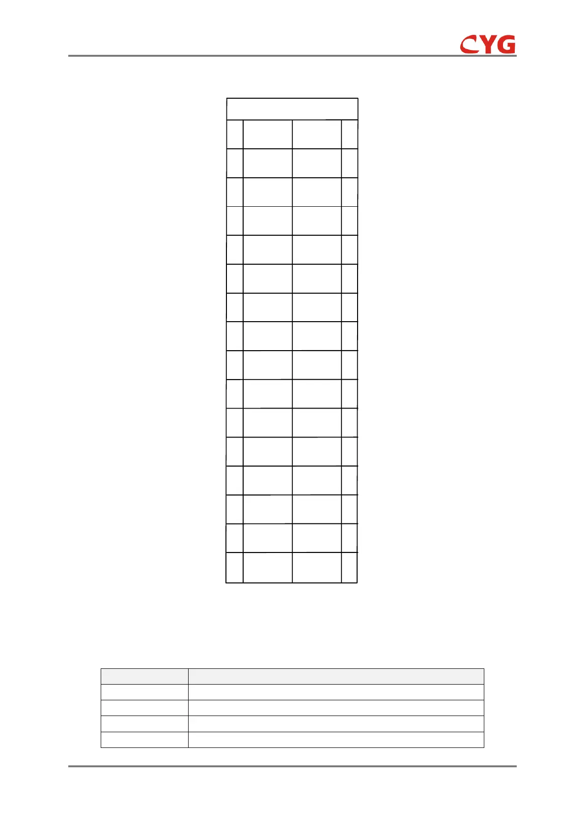
Figure 6.3-1 Frame of the Power Supply Module Terminals
The specific terminal definition of the connector is described as below.
Table 6.3-1 Terminal Definition and Description of PWR Module
Name
Description
POW+
Positive input of power supply for the device.
POW-
Negative input of power supply for the device.
Dev_Err Common
Device abnormality alarm common terminal.
Dev_Err Cls
Device abnormality alarm normal close terminal.

Table of Contents