MAN MACHINE INTERFACE
294 PRS-7367
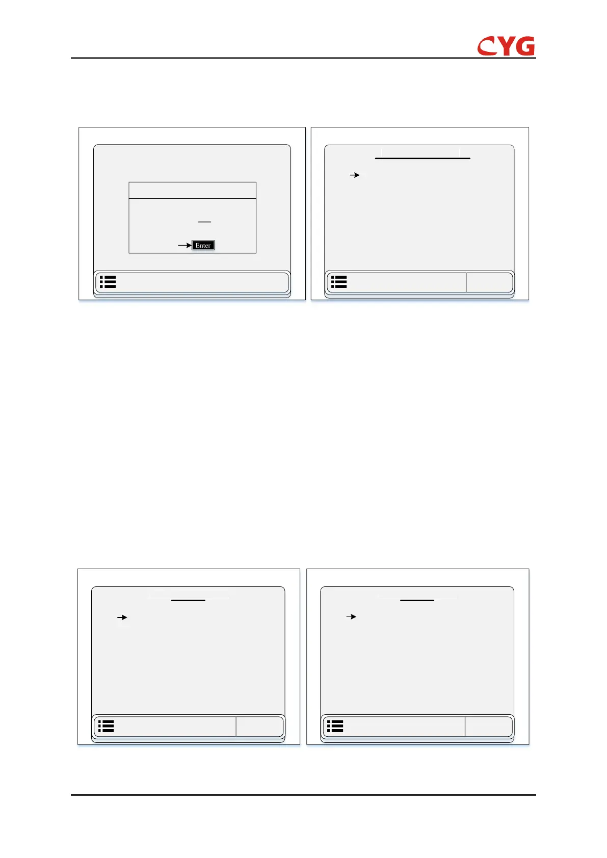
function through the following path: “Monitor > Harmonic”. The harmonic overview display diagram
of relay is listed in below figure 7.3.9. After the measurement channel is selected, the harmonic
data of the channel can be viewed.
Figure 7.3-9 LCD Display Diagram (a) Overview of Entrance Harmonic Monitoring Chart (b) Ua Harmonic
Content Display Chart of Page 1
7.3.3.3 BI
This section divided into two sub-parts and describe the information of binary input (BI) of this IED
seen in the above figure 7.3.5. This section only displays all the binary input data. User can access
this function through the following path: “Monitor > BI”.
1- BI
This part of single BI monitoring data contains 01 to 04 pages and 32 binary inputs. The BI display
diagram of the IED is listed in below figure 7.3.10 (a):
2- D-BI
D-BI is stand for double binary input function. The D-BI display diagram of relay is listed in below
figure 7.3.10 (b):
 Loading...